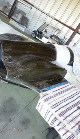
MOLDING NEW LOWER COWLING
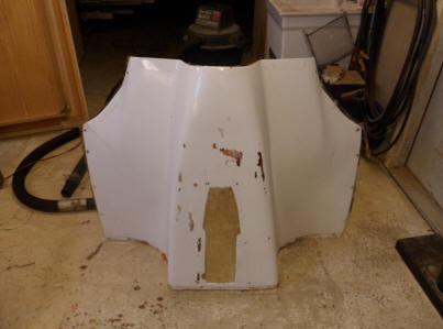
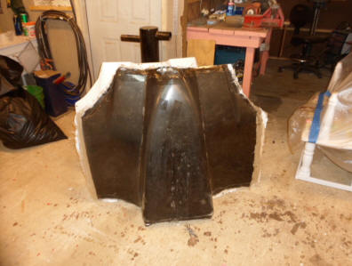
On the left you can see the old bottom cowling. We made a mold of that cowling and then laid carbon fiber in the new mold. We used a Fiberglass BID cloth then a thick layer of carbon fiber with multiple carbon fiber support reinforcements in the radiuses. Then we covered it with a finish layer of fiberglass BID cloth
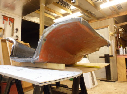
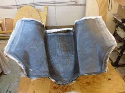
Above you can see the mold we made from fiberglass matt cloth. We waxed the old cowling with paste wax. never buffed it or removed any wax. We left it just like you would put wax on a car but very thick. Painted the old cowling with Toolmakers gel coat (Orange). We used brushes to paint it. Laid up the fiberglass over the gel coat painted cowling, waited 24 hours until it dried and the old cowling popped out of the new mold with no issues at all!!!
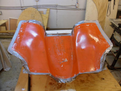
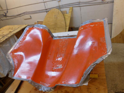
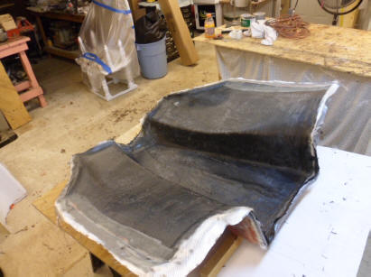
We prepped the new mold the same way, rubbed heavy paste wax all over the inside of the mold, never buffed it off. Then started laying our fiberglass and carbon fiber for the new cowling. The next morning the new cowling popped out like it was meant to with no issues at all. I mean like POP! I will never wax and then hand buff another mold after waxing. every time I do it, It takes me forever to get the part out and I end up cracking something.
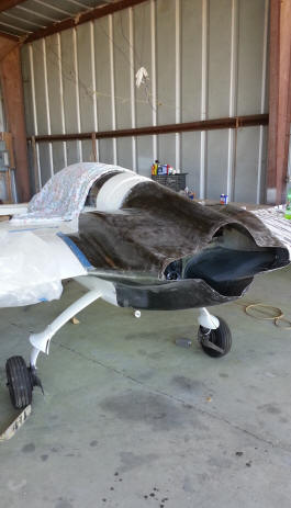
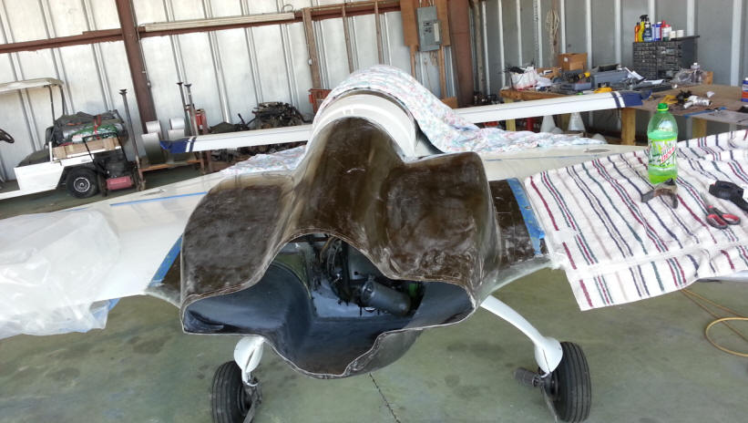
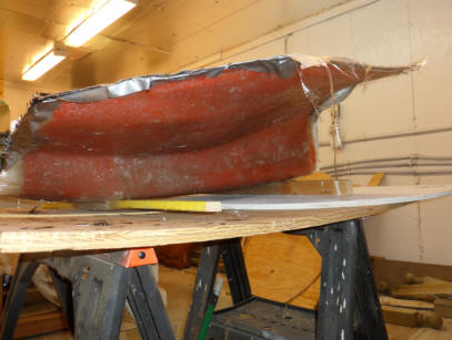
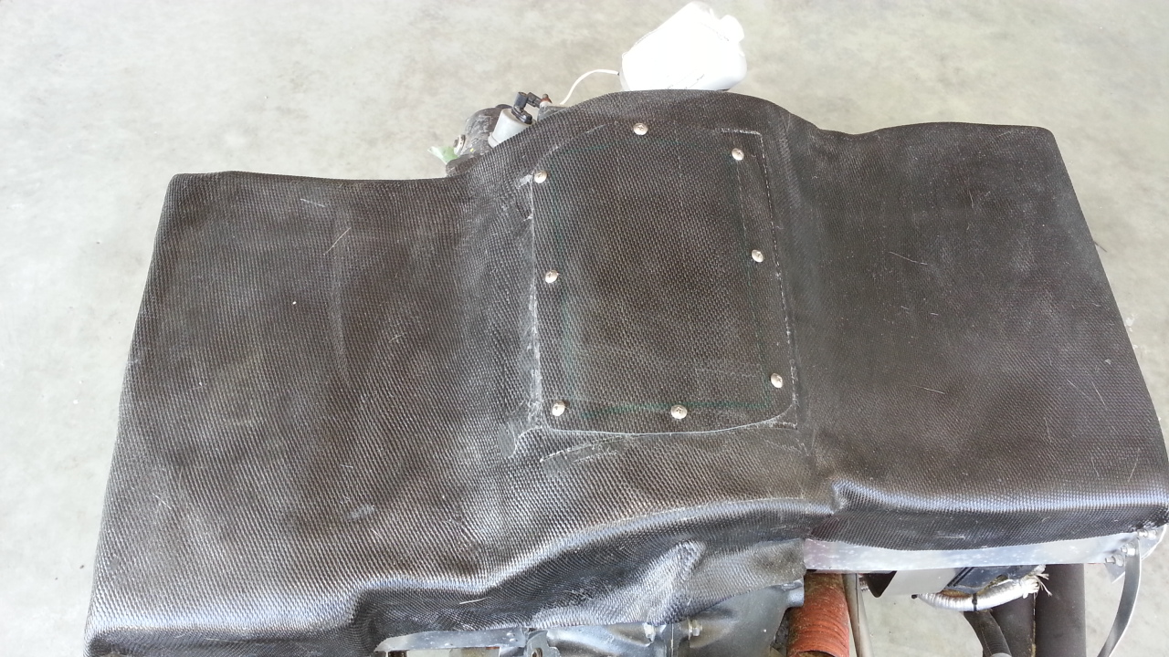
Now it was time to start fitting the New Carbon Fiber upper and lower cowlings together and mating them to the airframe and wings. I had made the upper cowling several years back with Craig and Joe Gearhart. I am just now installing it with the new lower that Tom Carey helped me make. Don't worry about the wrinkles on the lower cowling, they get trimmed off as both cowlings are about 3 inches too long. After fitting them individually to the airframe. I then fitted them together at the rear and glassed them together as one part.
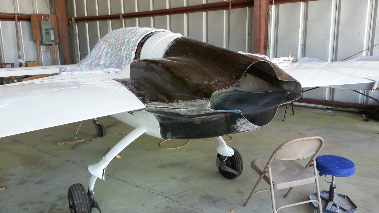
If you notice the cowlings are no longer glassed together. A seam has been cut between the upper and lower cowls. They now have a clean parting line. They have been trimmed and the excess material has been removed from the rear. The upper and lower cowlings have the joining tabs glassed on the inside rear at both sides so they can be rejoined together. All that is left is some sanding and filler work, prime and paint.
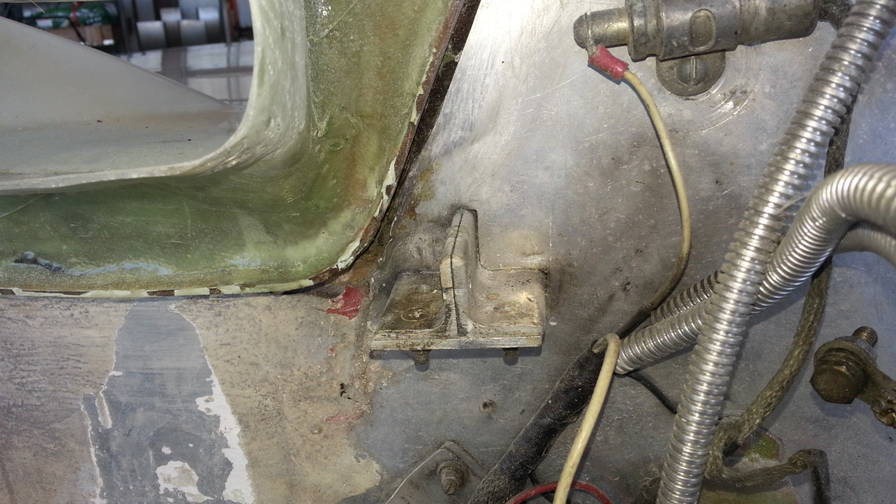
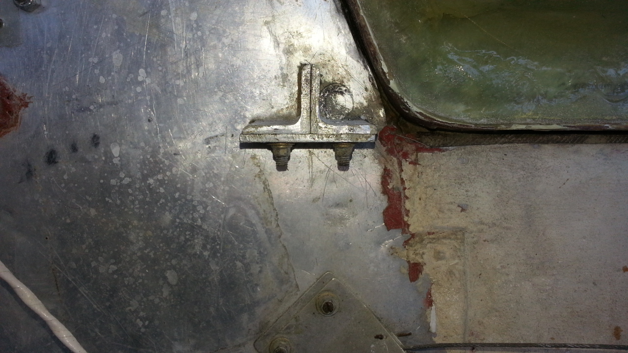
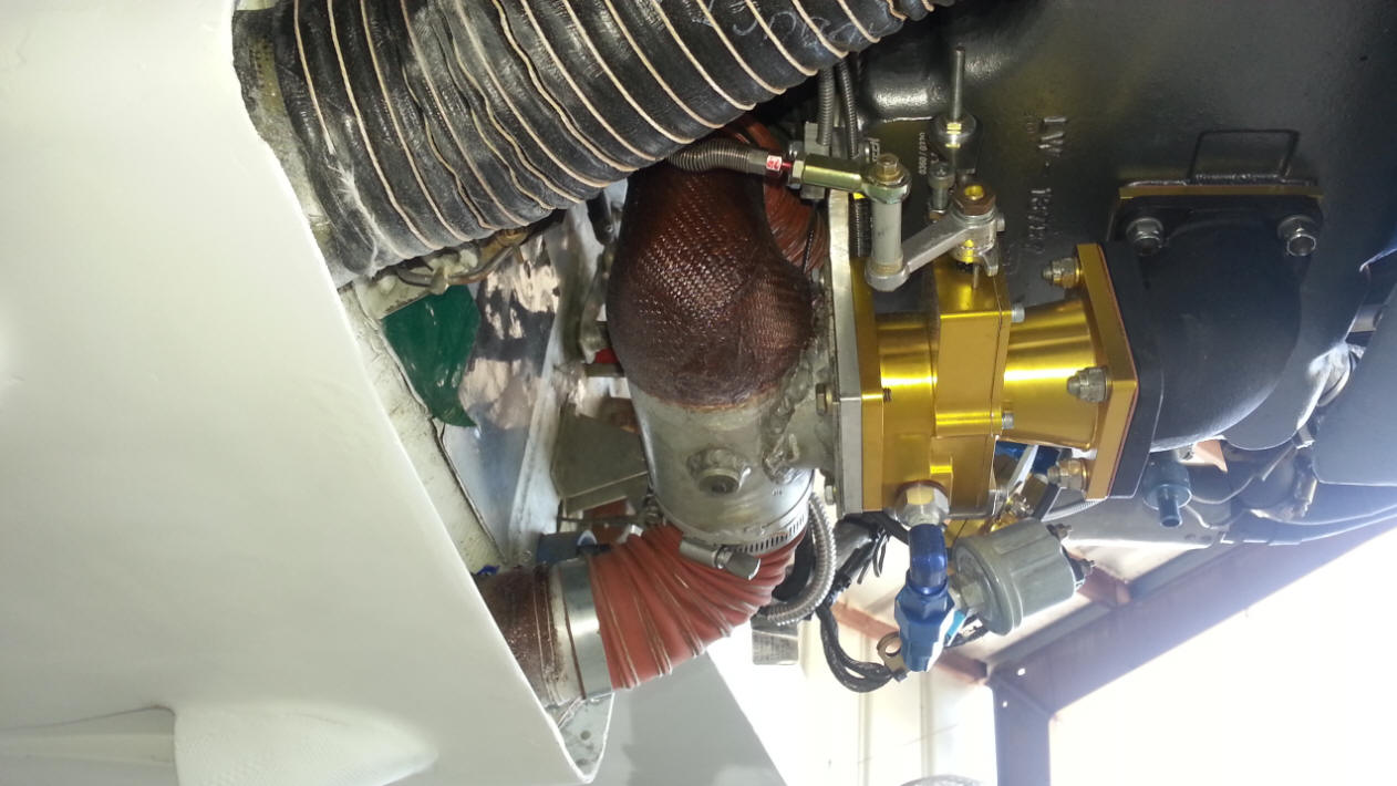
ENGINE MOUNT CRACK
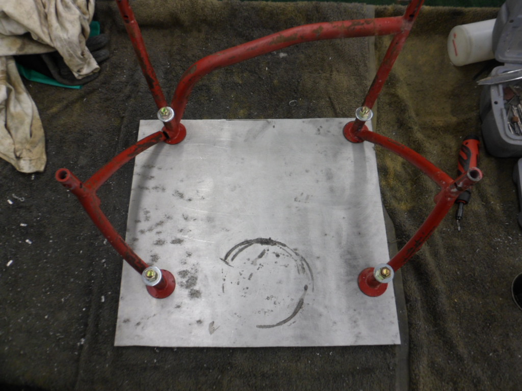
So, I am looking under the engine for a vacuum tube leak and I notice this CRACK on my engine mount. So its time to repair and or order a new mount. I had just inspected this area about 6 hours of flight earlier and everything was fine. It just goes to show you that you can never preflight enough or inspect enough to catch everything.
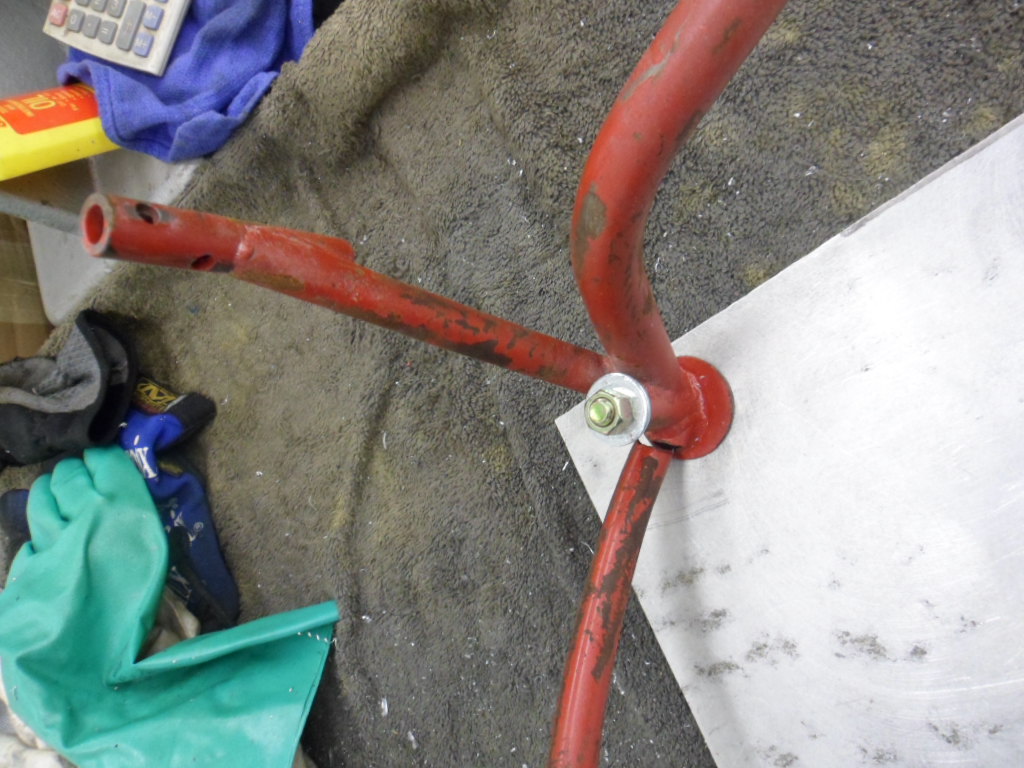
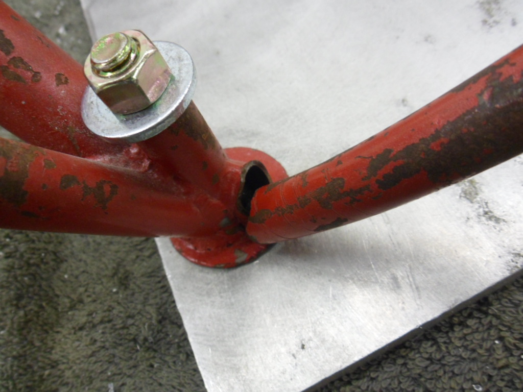
I used the aluminum plate as a jig so the mount could be repaired as though it was mounted on the engine. The cracked mount was re-welded and gussets were also added by a local tig welder. It is now a standby secondary mount. The new mount was ordered from the Cozy Girls and should be arriving in 2 -3 weeks. I would use the old mount but it is not that robust and may crack again due to the light weight thin walled tubing that was used when it was built. I am sure it would work fine for an 0290 or 0235. The 0320 has a little to much torque for this lightweight mount.
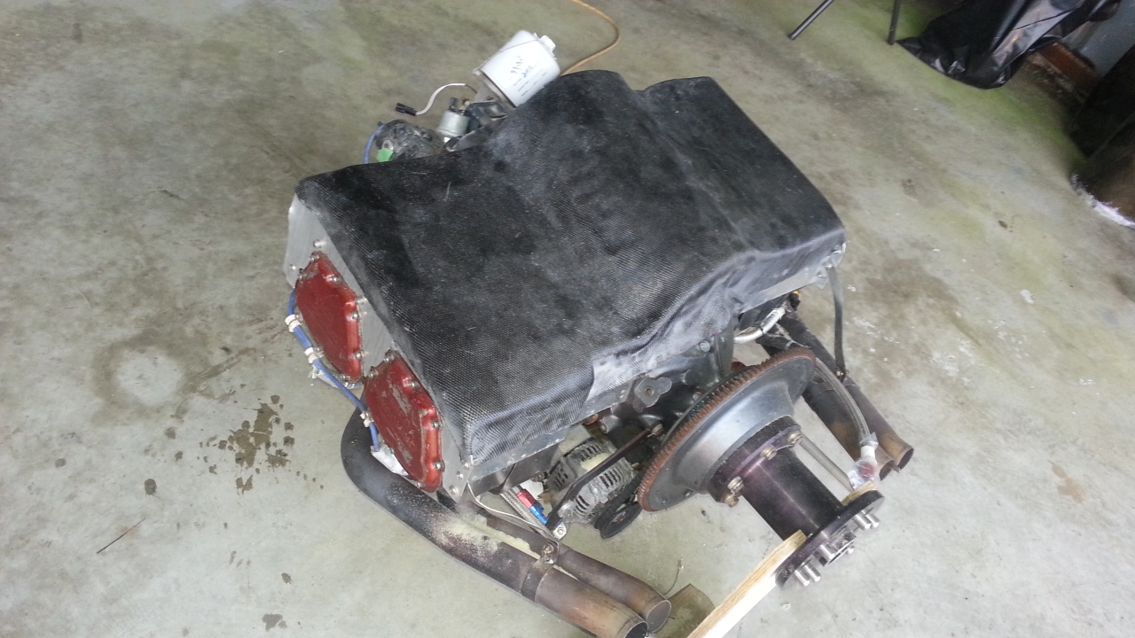
ENGINE PLENUM FOR COOLING
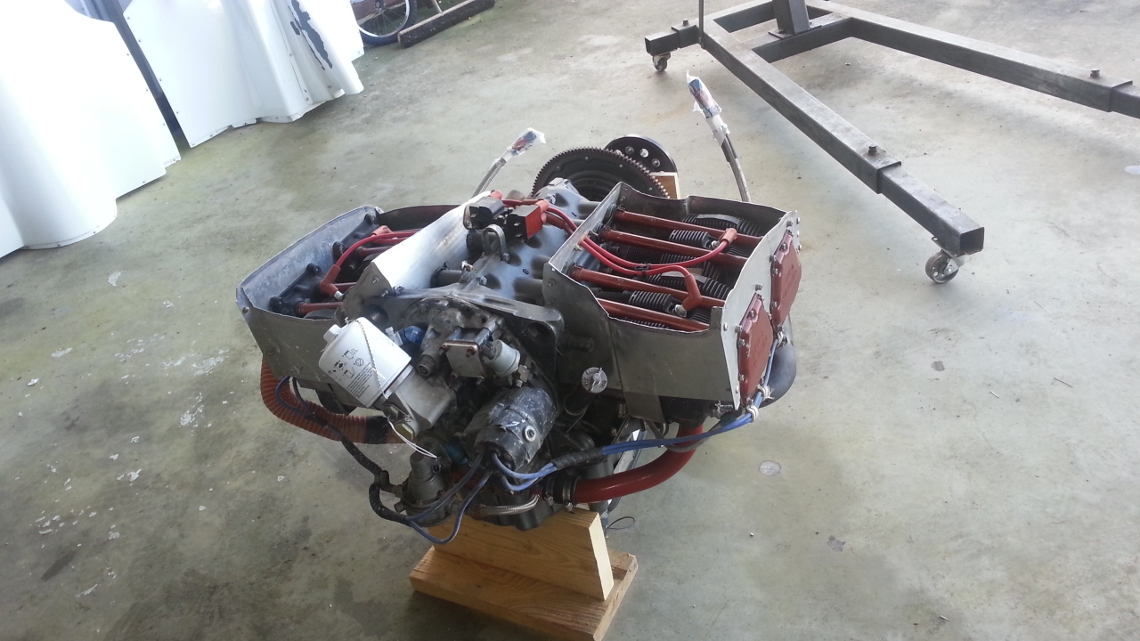
There she sets with the old metal baffling. I decided that as long as I had the engine off the plane I might as well make a carbon fiber plenum to keep it cool. So I started with the pore-a-foam! If you have never used this stuff you're in for a treat when you do! Once you get it on you it never comes off. In addition, you never know what to expect or where its going to go when it starts to expand...
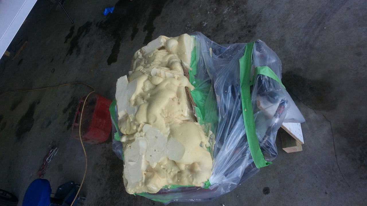
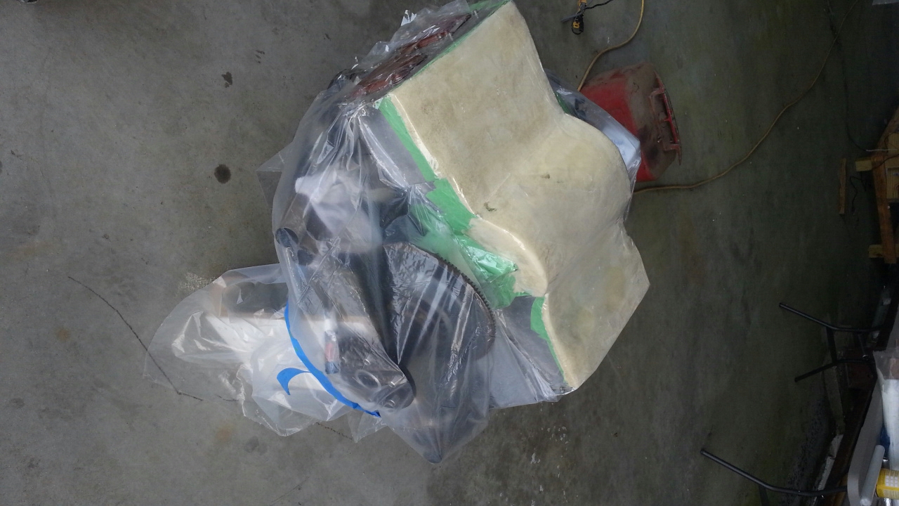
You can see all the pore-a-foam on the engine and then what it looked like after I sanded and shaped it into the new plenum cover. I covered the foam core with wax paper and packing tape so when I laid the carbon fiber on the foam shape it would not stick to it.
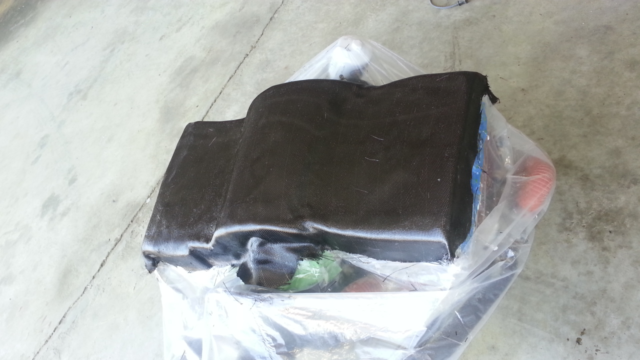
When the carbon fiber cloth dried I just pulled it up off the covered foam core and didn't have to scrape foam out of my new cover. The second picture was after trimming the dried carbon fiber plenum top. The most difficult part of glass work for me is having to wait 24 hours before I can do anything with it. I'm a bit impatient.
The last picture is with an access cover on the top to get at Coils and plug wires of the electronic ignition. It doesn't look like it but if fits like a wet leather glove and is very rigid. I'll complete some final trimming and add fastener locations before its installed in the plane.
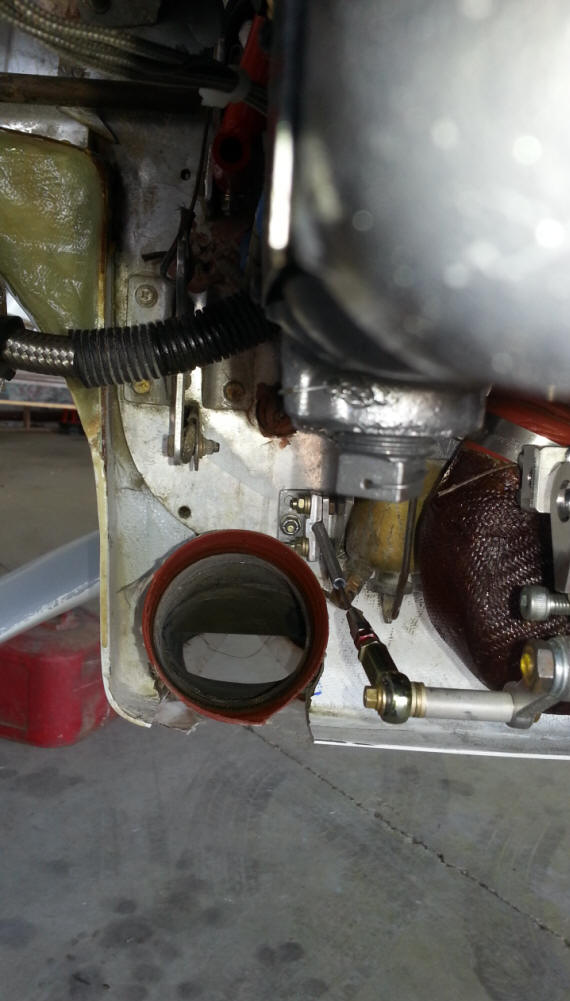
OIL SITE WINDOW IN SUMP
I have always wanted to just walk behind the bird and look in at the oil sump to see if I had enough oil to go fly. Well now I can! I can just look in the rear of the cowlings and see if the sump has at least 5.5 qts of oil in it. Yes the 5.6 level is just at the base of the sight glass window. I pored fluid in the sump before drilling the holes and welding the boss on it to determine exactly where 5.5 qts was. Interesting note: 6 quarts is at the upper lip of the sump. 6 qts, 1 oz will overflow the the sump. I have no idea where LYCOMING gets 8 quarts. I know the dipstick says 8 quarts but? 8 quarts puts you into the case and the crankshaft has to push all that draggy oil around!!! I know why Lycoming's always spit out everything but 6 quarts, the crank turns it into mist and pushes it out of the breather. I also installed an oil level switch on the other side of the sump to let me know if oil level dips below 4.7 quarts.
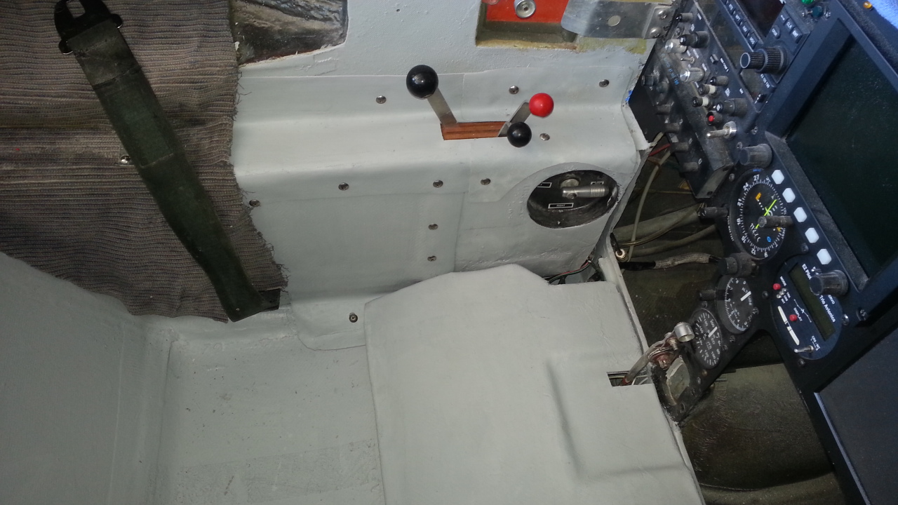
NEW THROTTLE QUADRANT
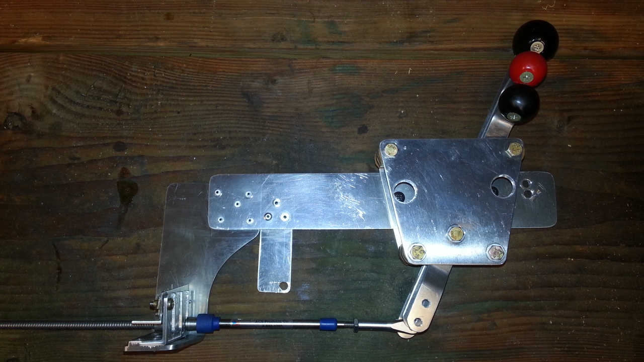
I always disliked the plans installed Throttle Quadrant on the Long EZ. It was small, hard to grab the little knobs and used bicycle cables to pull the Mixture, throttle and carb heat. There was no pushing , that was all done by springs you had to rig on all the parts the cables attached to. It was not safe and you never had positive control. I finally decided enough was enough and installed a real aircraft throttle quadrant that pushed and pulled the critical fuel controls and carb heat.
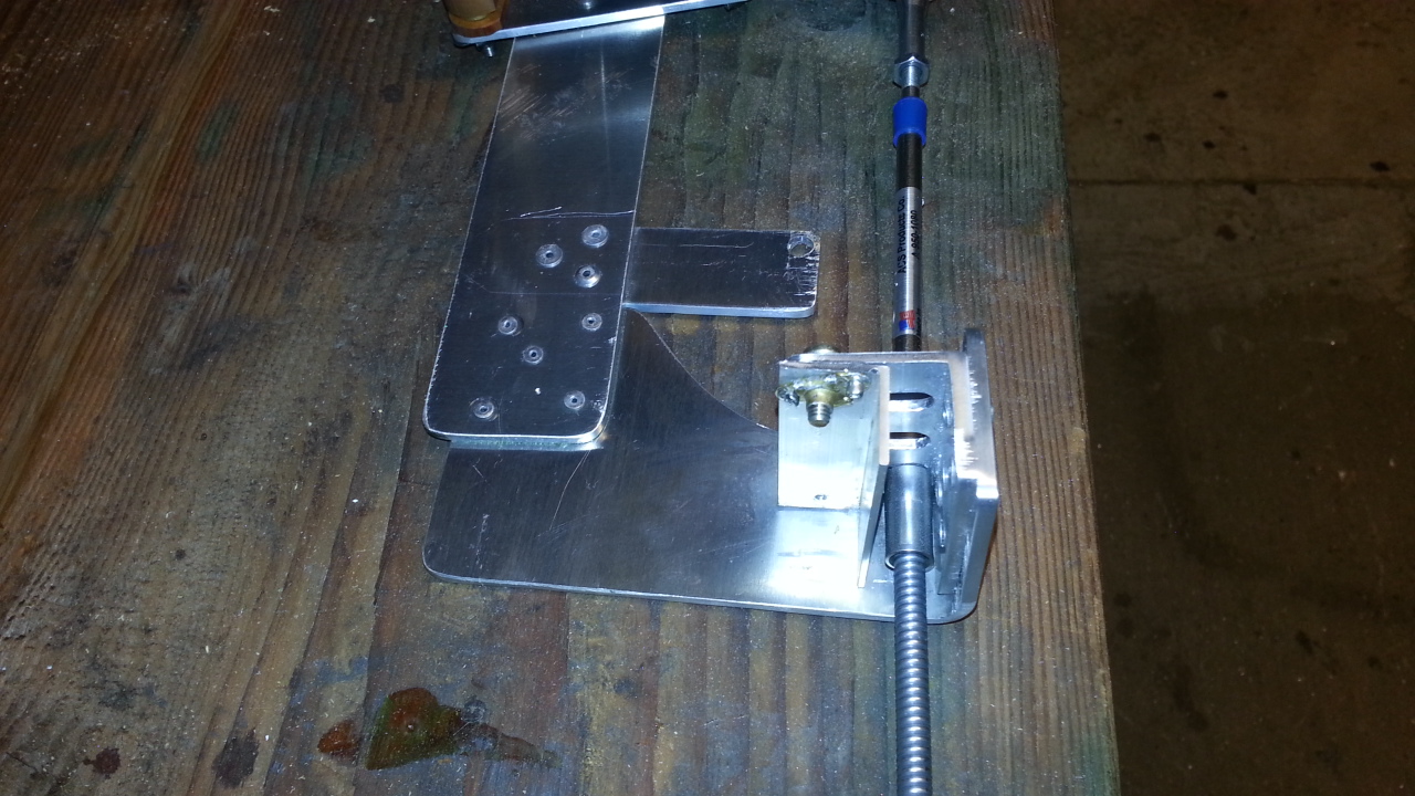
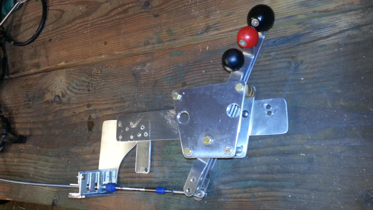
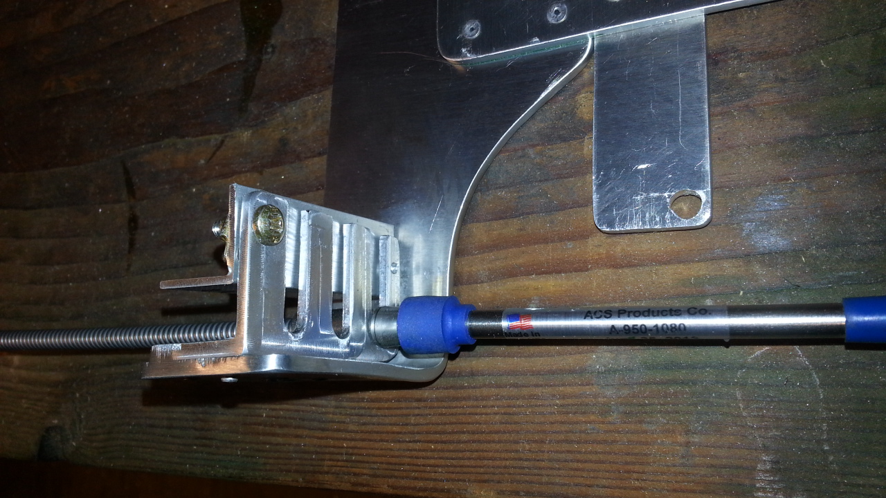
I designed the mounting of this new quadrant to be simple, 2 bolts hold it in place and the cables would just drop in and lock into the holder with very little effort. In addition I needed this to fit in a very small (tight) area just behind my fuel control valve. Plus , it's a glass airplane and I did not want to glass this stuff in as I wanted to be able to access it to service it if required.
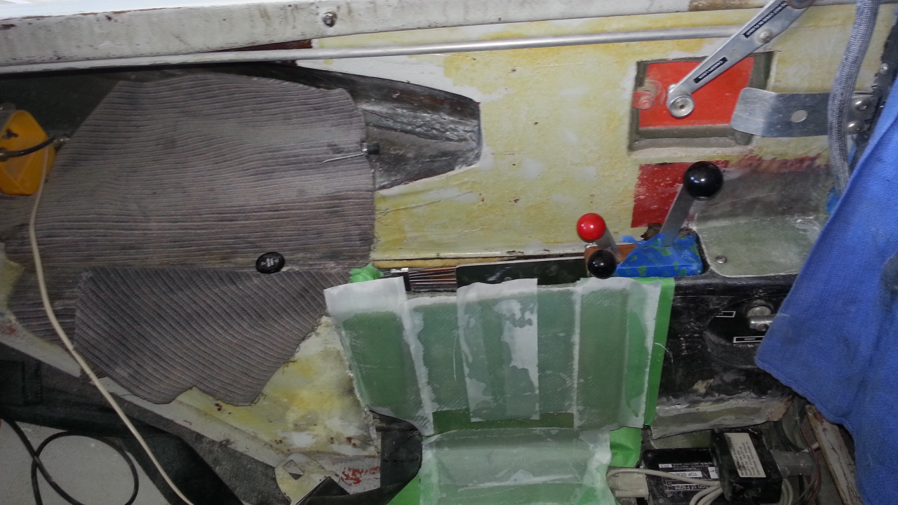
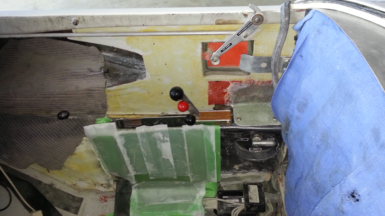
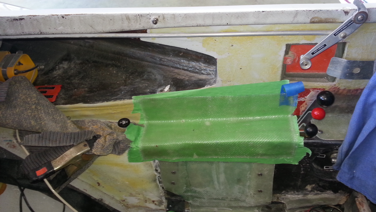
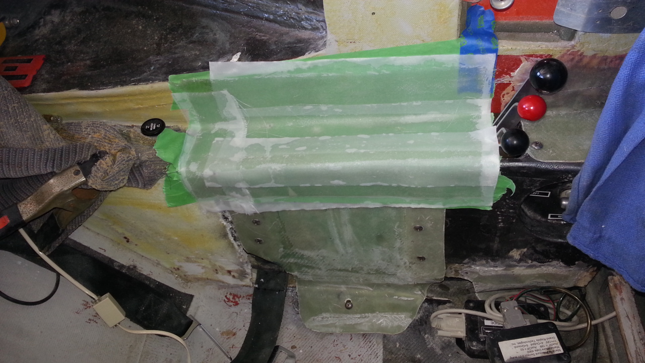
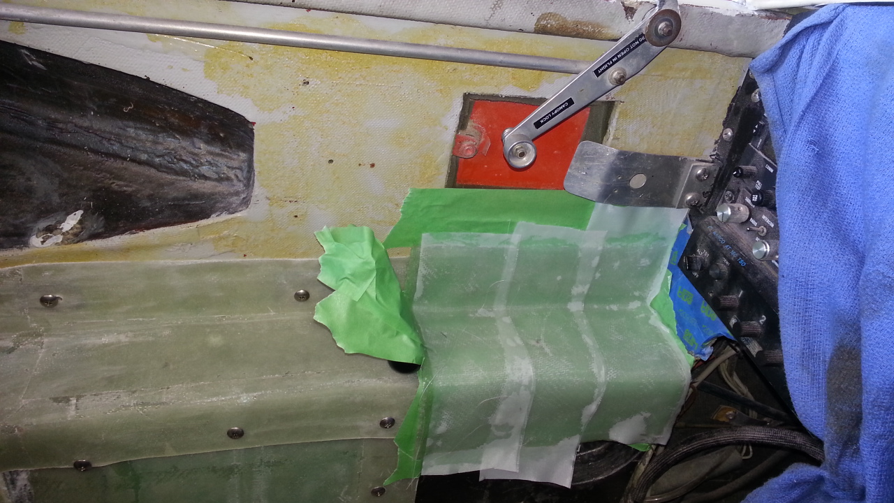
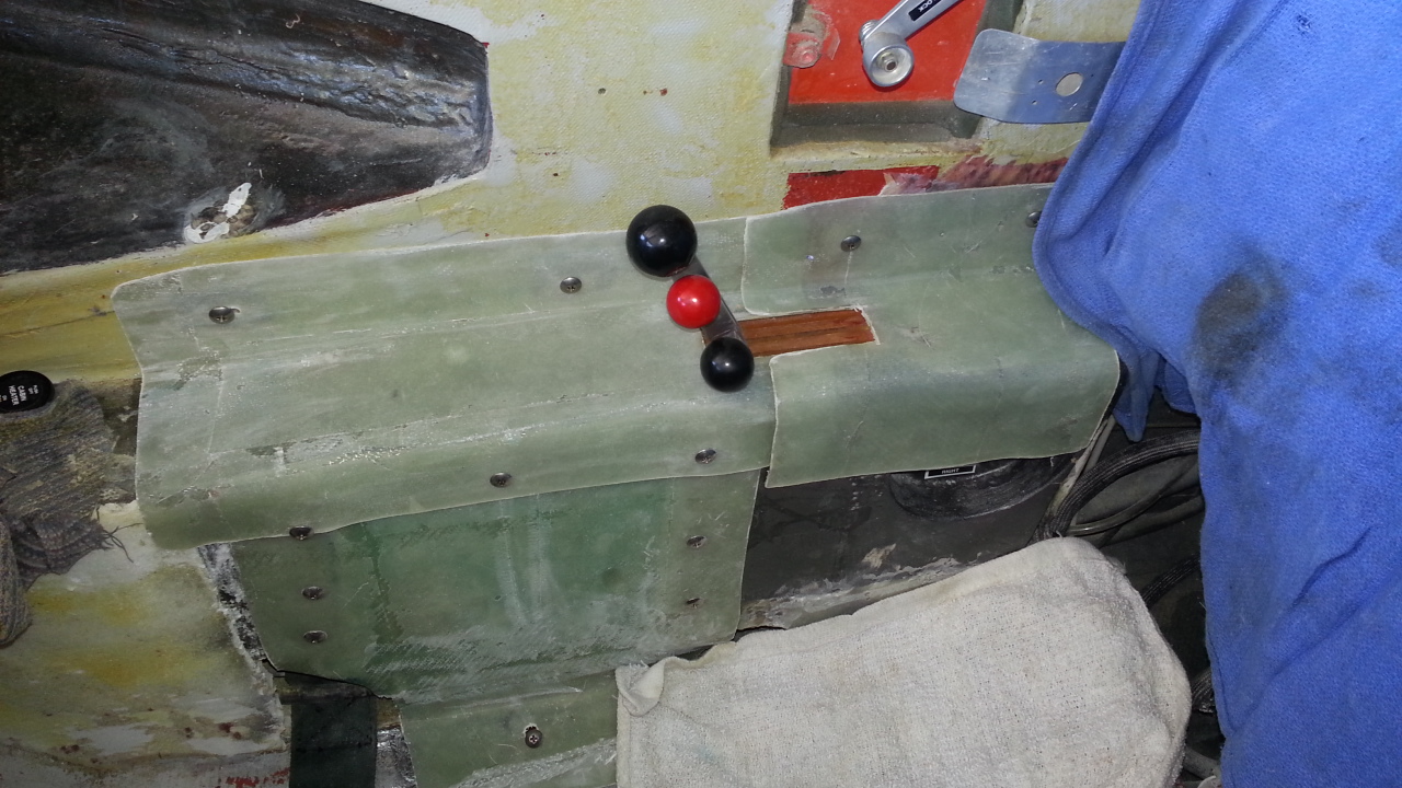
I made all the panels that held the throttle assembly so they could be removed. they are held together with hard point fasteners and rib nuts. It takes about 5 minutes to remove everything to get access to the fuel valve or throttle quadrant.
Everything assembled and in primer. I will complete the interior with a light weight leather fabric covering later this fall. The best part of this modification is, NO MORE Tiny throttle quadrant with bicycle cables!
NEW WING ROOT BEARINGS
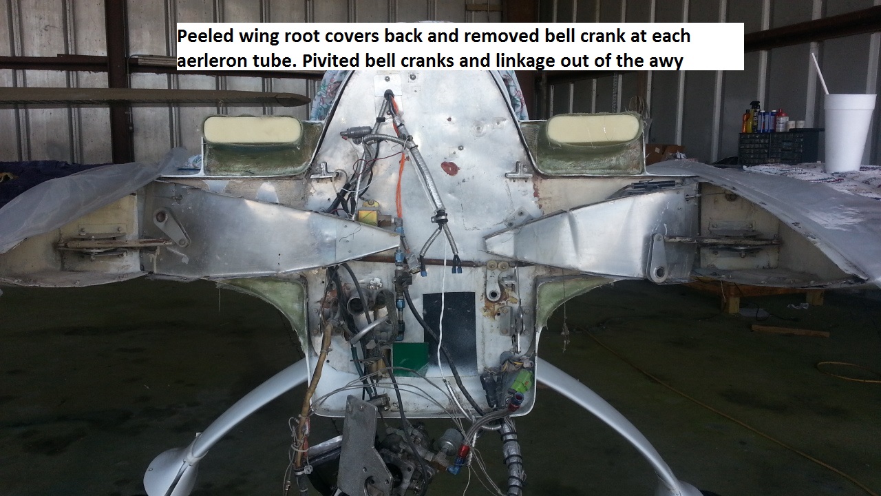
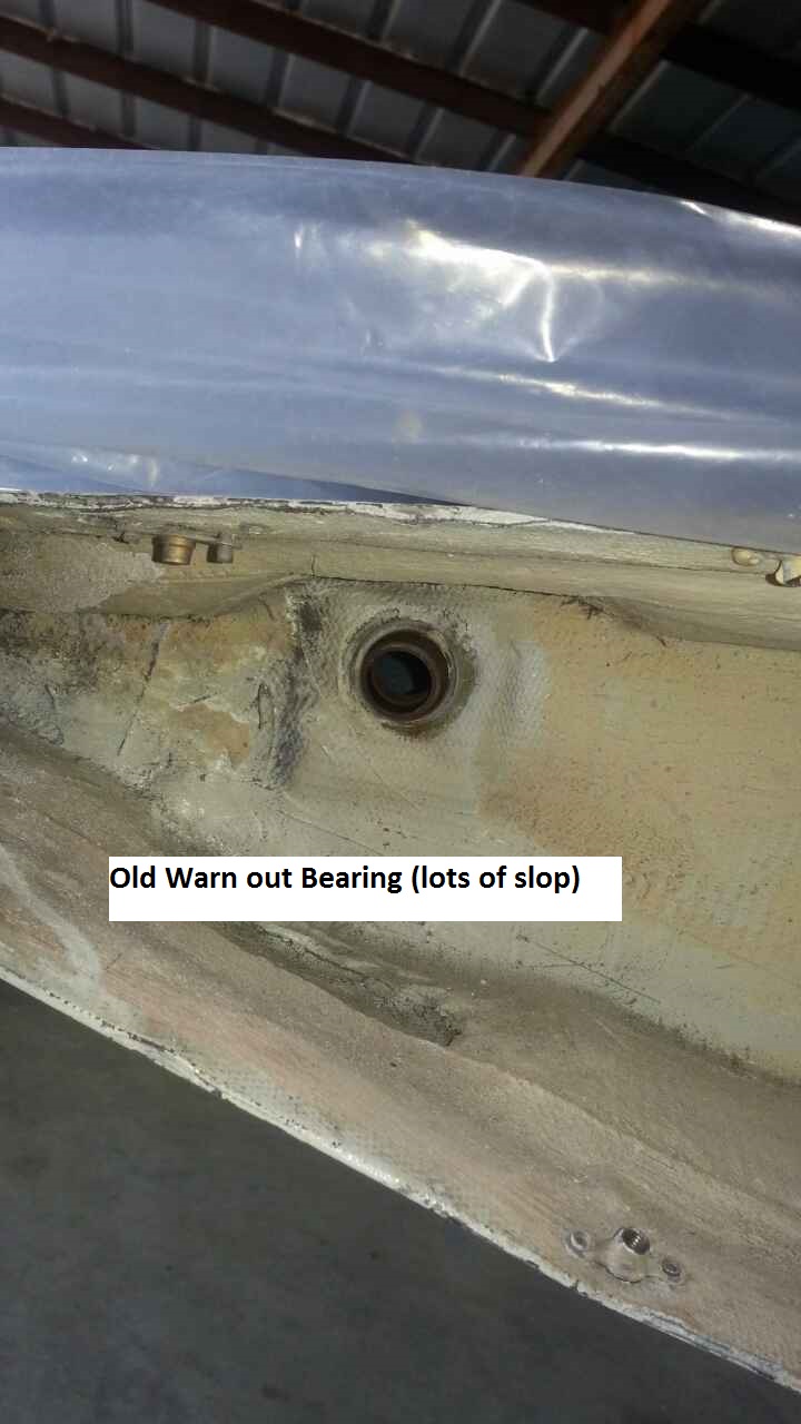
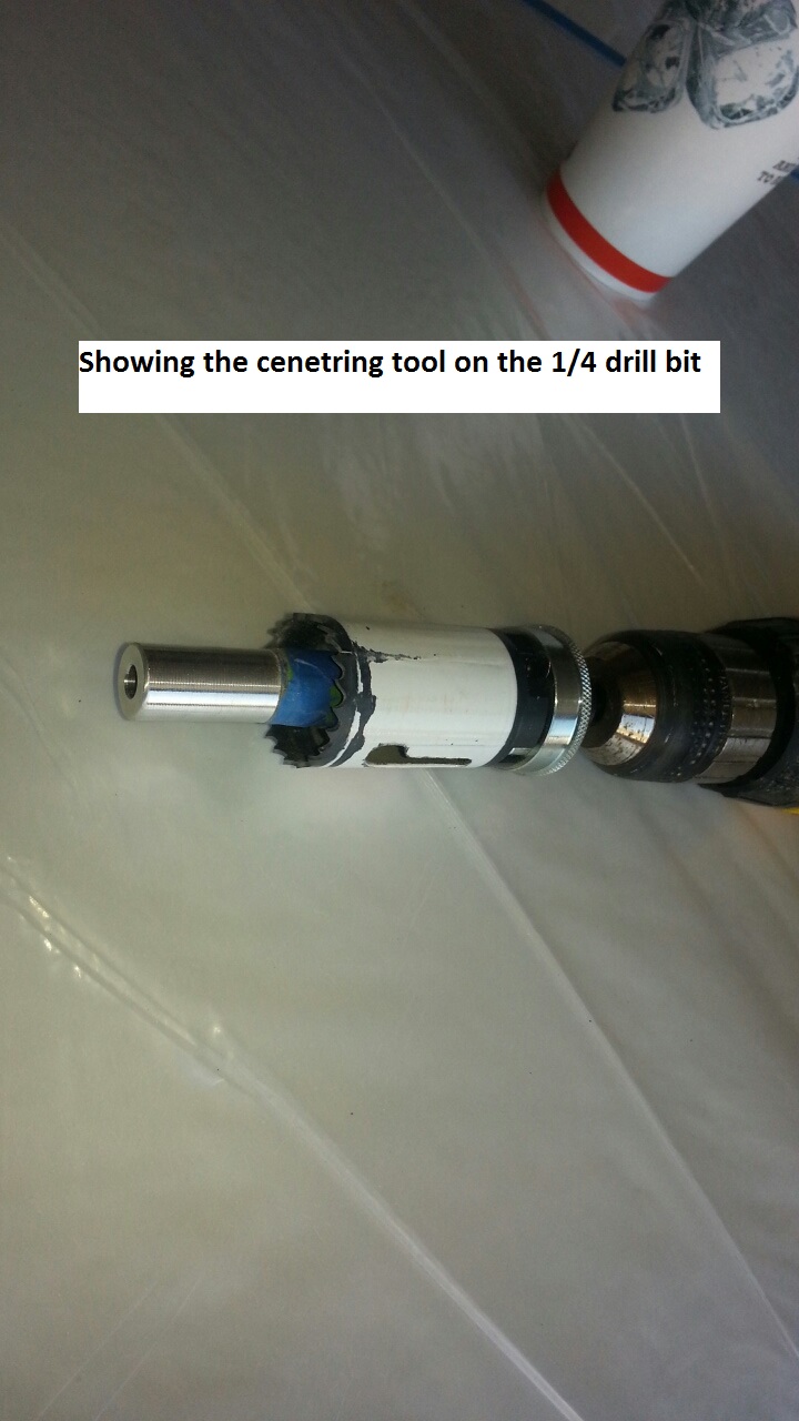
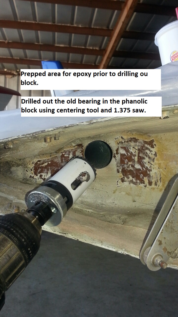
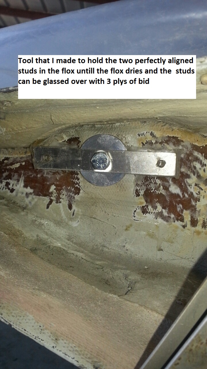
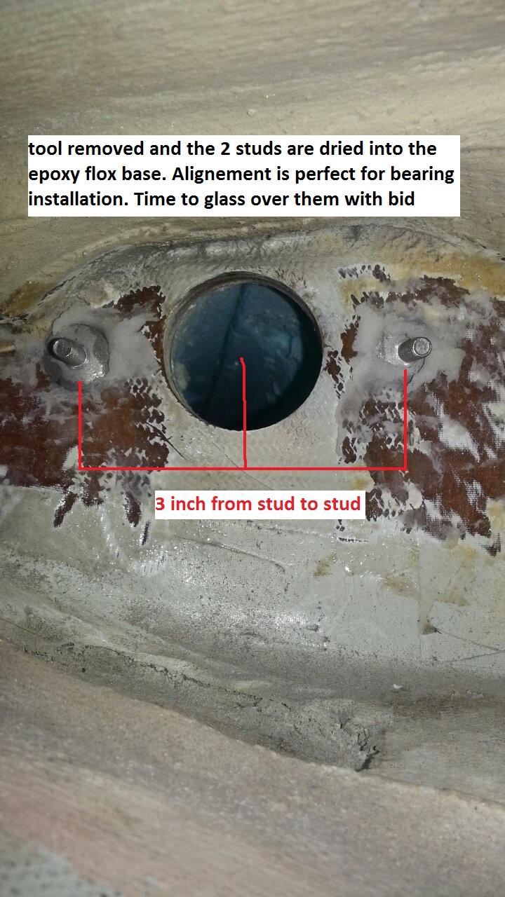
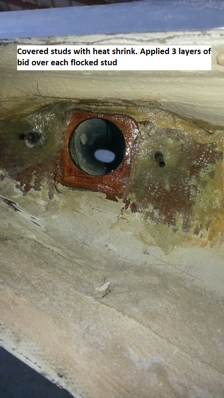
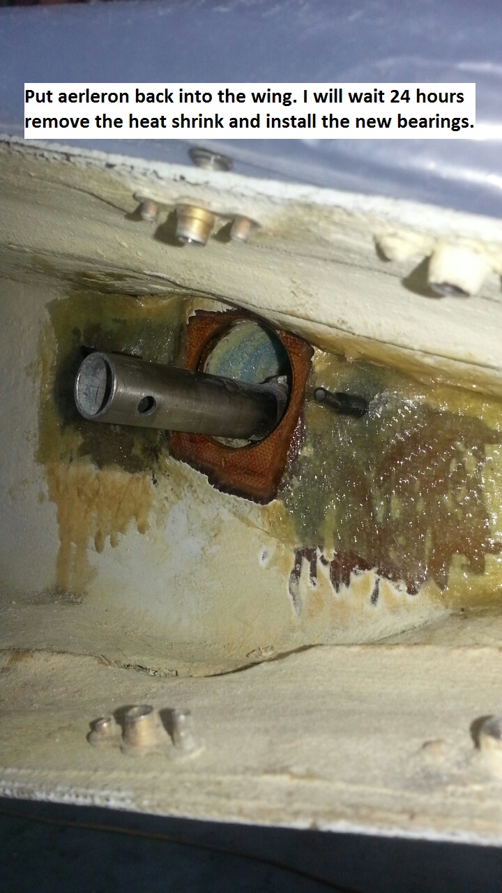
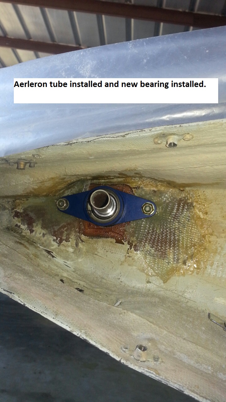
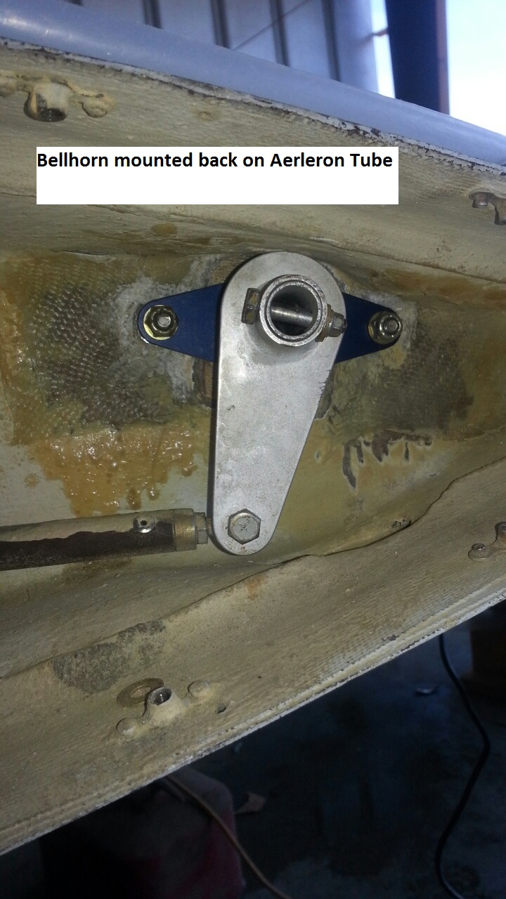
Changing the wing root bearings was not difficult, just very time consuming. You had to wait 24 hours between glassing and floxing the studs in. I made the centering tool to fit in the middle of the old warn out bearing so when the hole saw started to cut it wouldn't wonder. The special tool I made held the two studs in place at 90 degree angles until the flox dried the next day. That allowed me to slip the bearing over the studs making sure the spacing or angles didn't change prior to the epoxy setting up. So as long as I was in the wing roots I also changed out all the Heim bearing ends and one universal joint on the aileron tube at $109.00. The Heim bearings were 21.00 each and it required 4 for each aileron control (8) total.
BROKEN NOSE REST
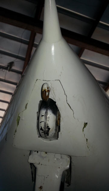
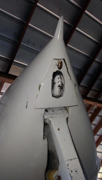
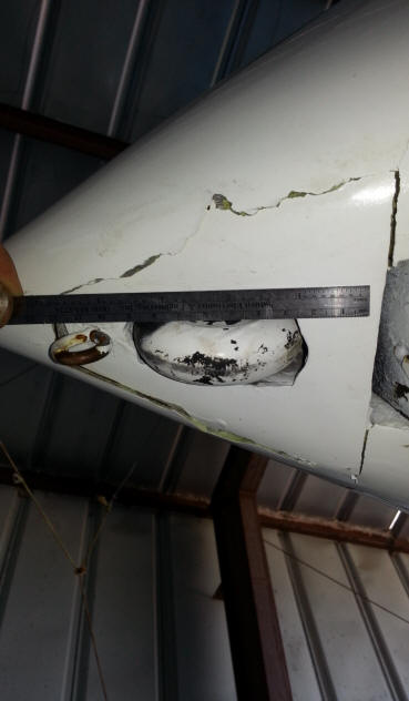
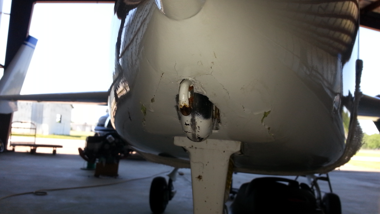
This is a prime example as to why you should put a sign on your airplane that says "DO NOT TRY AND MOVE"! People have no idea how to handle a Long EZ or Veri EZ and they can end up on their ass or have the nose drop and bust up the underside. I have no idea who did this to my plane . I think someone tried to move it and set the nose down, when it started getting heavy they just dropped it. I was going to fix this but have decided to just have the EZ JET shop fix it as they are installing the new engine extrusions on the main spar for me. The ones on the airframe are the plans engine mount extrusions and they are a bit light for the engine I am strapping on.
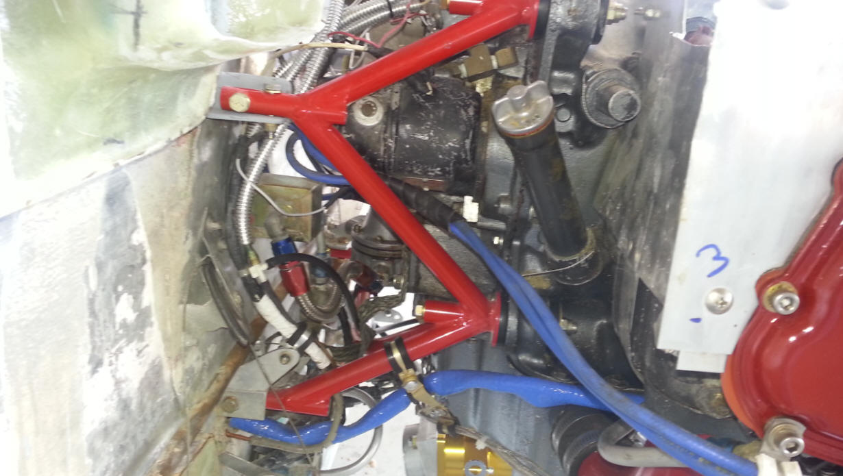
TWISTED ENGINE EXTRUSION
You can see that the mount on the left has a slight twist to it. It was getting overstressed.
You can clearly see that the mount on the left has been tweaked a bit. The one on the right was still in good shape. EZ JET (Rob and Valerie Harris) are going to install new mounts to the main spare. Rob said he was going with steel extrusions so there would be no change in engine position / location and they would be extremely strong. I thought about doing the mounts myself but decided that I should let an expert install them. Rob has made this upgrade half a dozen times and has been working on canards since 1974. I feel very good about trusting his work and expertise.
New Engine Mount installed on new Steel Upper Engine Extrusions.
There will be no more twisting or cracking!
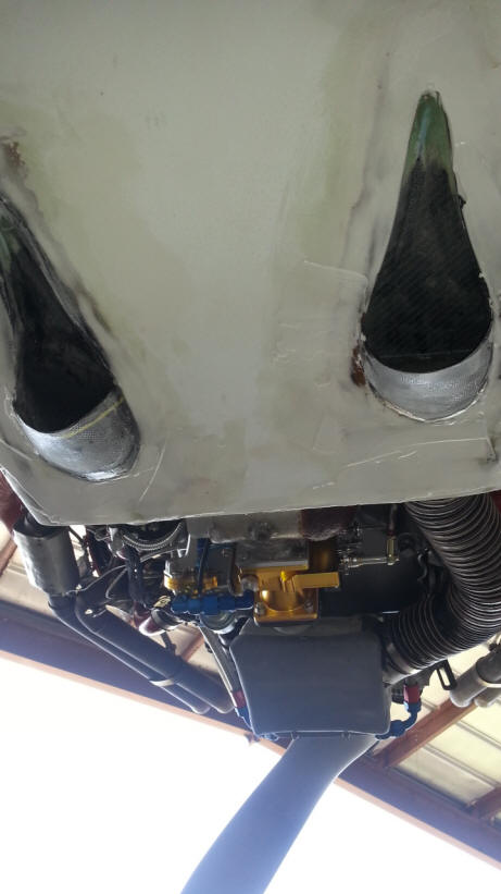
TBI and OIL COOLER INLETS
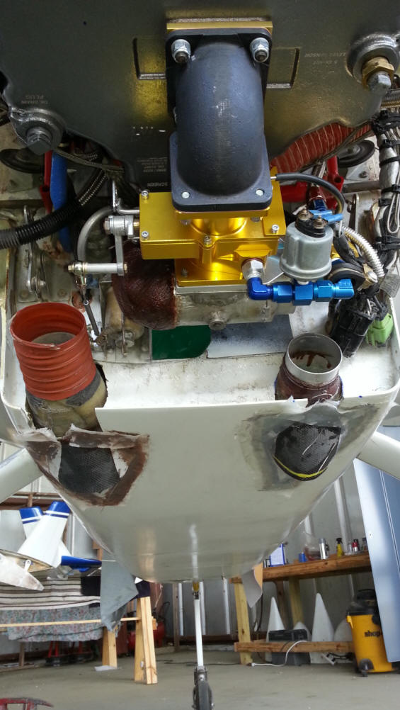
Initial Installation of the pre formed NACA scoops. The one on the left with Sceet tubing on it is a 3.0 inch Diameter. It will feed the oil cooler. The smaller one on the right is a 2.5 inch Diameter, it will feed the new ROTEC TBI. The added half moon scoops will ensure I have enough airflow. I can always remove the ram air scoops once the concept is validated and I have enough cooling and induction airflow.
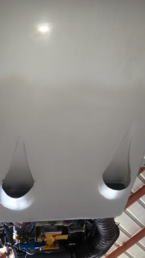
I will cut the half moon scoop off if there is to much airflow.
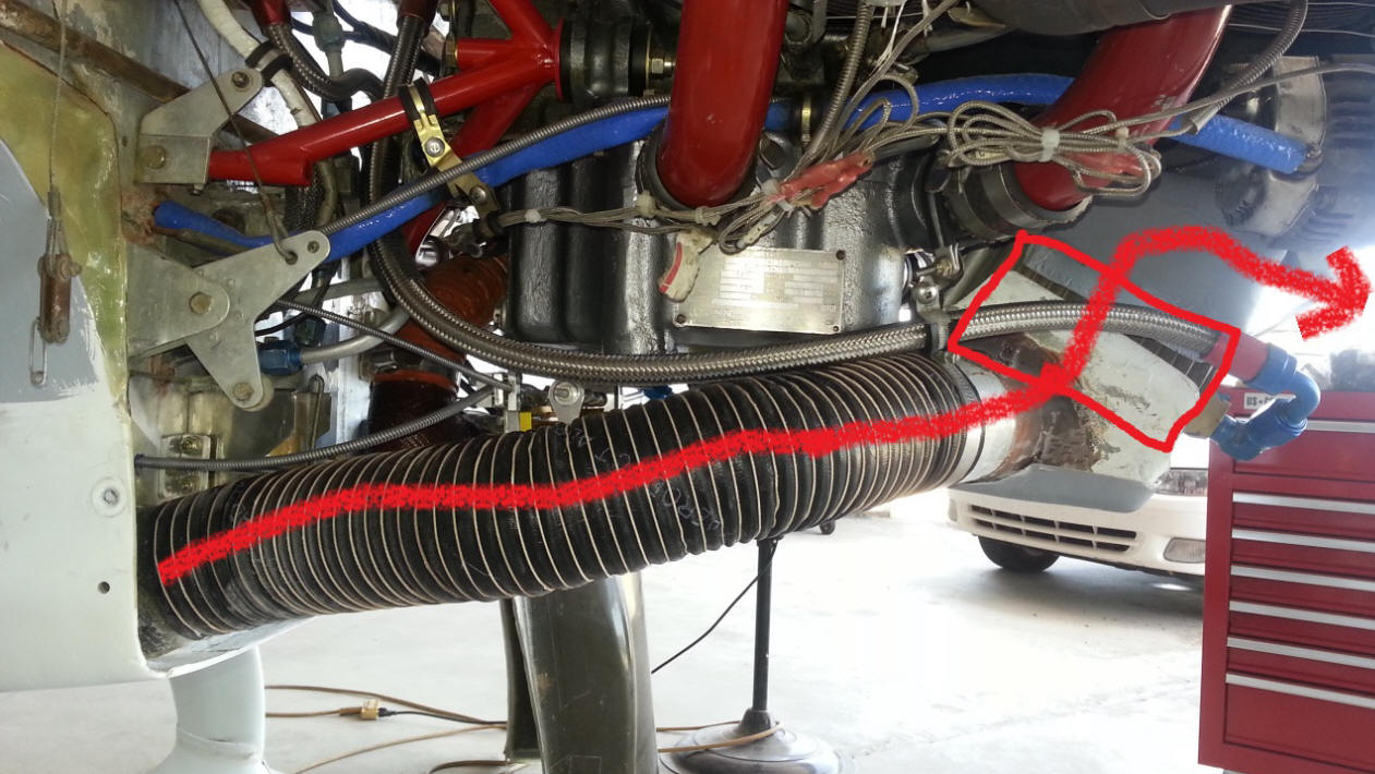
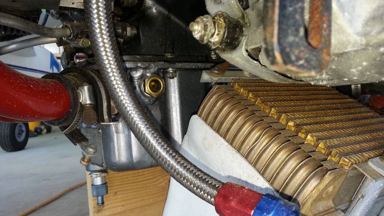
You can see the path of the oil cooler air flow
TBI is fed off the 2.5 inch sceet tube and right NACA inlet
P2 engine Install P3 Upper Cowl P4 Lower Cowl P5 SPL Parts P6 Flt Pics P7 More Pics P8 Bio Info