
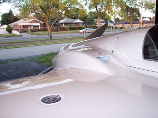
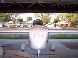
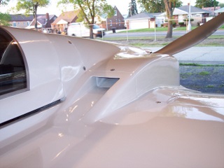
Downdraft air inlets at top of cowl. Both designed to be efficient and
eliminate excess drag
STATS FOR LONG EZ N55GR
Cruise Speed: 172 kts Indicated AS 3500 ft MSL 68 degrees F
WOT 187 kts Indicated AS 2500 ft MSL 72 degrees F
Empty weight 1006 lbs
Climb Performance 1800 ft per minute to 5000 ft
Ceiling 14000 ft. W / OXYGEN on board 25,000 ft
Fuel 50 US gallons (25 per side)
Range 1100 Nautical Miles
Cruise Gallons per hr 8.2 GPH
WOT Gallons per hr 13.0 GPH
Seats 2 (pilot & passenger)
Engine 320 Cubic Inch apposed 4 cylinder Lycoming
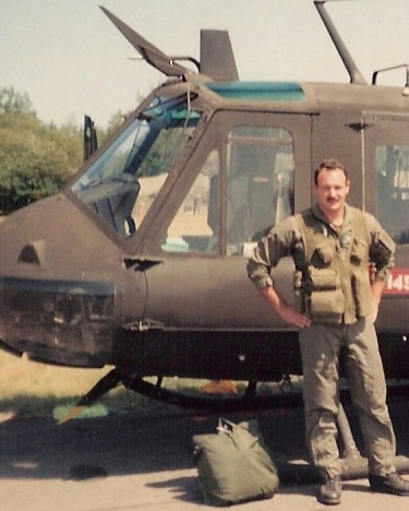
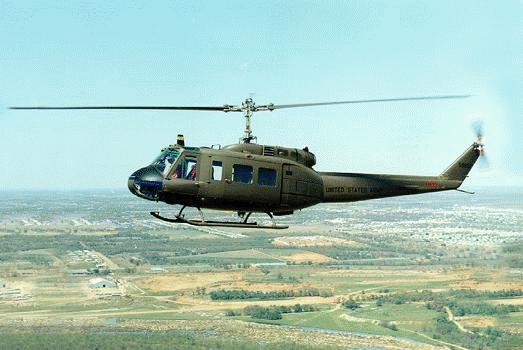
A little bit about my aviation background: Commercial Instrument Pilot: Turbine Helicopters and
Multi Engine Airplanes, US ARMY: Test Pilot Bell Helicopters, UH-1 Line Pilot, A&P Mechanic. Started in aviation 1982
going on 30 years of experience as a 3D driver, Experimental Aircraft owner
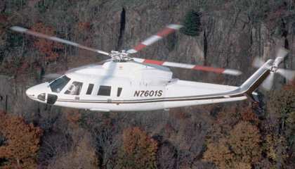
S-76, I flew one of
these for Domino's Pizza, just an incredible bird to pull pitch on
!!!
I want to talk a little bit about performance. Top of Page
Some members of the flying community don't fully understand airspeed. There are those that only talk in true airspeed and then others who speak in an even more convoluted language, groundspeed (GPS verified). I like to talk in Indicated Airspeed in Knots, not Miles Per Hour. To clear things up, each knot is equivalent to 1.150779 mph.
The reason I like to talk in knots and indicated airspeed it they are honest, non exaggerated numbers. When ATC says "report speed or slow to" they are talking about indicated speed in knots. I've never in 23 years of flying heard a controller say report true airspeed, slow to this true airspeed or accelerate to this true airspeed. Are you getting my point here? At no time have I ever heard ATC use the term MPH. It's expected that you report in Knots and indicate speed. That means you report exactly what the airspeed indicator is showing.
When you ask most pilots the Top Speed of their airplane they always use true airspeed and like to report it in MPH without saying MPH. I'll give you an example. I asked a fellow and very respected Long EZ pilot (20 year owner and builder) what the top speed of his airplane was. He stated "I don't know I've never looked" It was hard for me not call him out on his reply. Any male that owns an airplane, racecar, boat or even a snowmobile can tell you within the first few rides how fast it is. Its' one of the first things we do as males, FULL THROTTLE and see what we get. Aircraft owners do this the first flight. After all, we have no speed limits! Well, after probing him for a few minutes he says "I guess around 200 or so.". I say "200 what"? After some him-in and haw-in he says MPH. I ask, is that true airspeed or indicated airspeed. He says true. So my next question was "what was your indicated airspeed". He said I don't know I never look at indicated speed. Now for those of you that don't understand how this works, there is a mandated gage by the FAA in your aircraft it's usually about 3.125 inches in diameter and sets 18 inches in front of your face. It's called and airspeed indicator! In order for anyone to compute TRUE AIRSPEED you must have INDICATED SPEED FROM THE GAGE, Temperature and Altitude. Not to mention that this guy built and flew this plane for 20 years and expects me to believe he never looks at his airspeed indicator. His rational for this was he had a digital true airspeed converter in the plane he used. Bottom line, his 200 mph true was equal to 167 knots indicated airspeed. It took me forever and a day to get that out of him. Pilots just don't like to admit they have an average speed or slow airplane. Especially in the Canard community.
The reason I got into the airspeed subject is this; N55GR can produce enough prop thrust to reach 187 knots indicated airspeed. That equates to 215 mph indicated or if I was to use true airspeed it would be 194 Knots or 223.7 MPH. That equates to Four (4) different speeds I could tell people and never mention MPH, Knots or True. All aircraft manufactures use True airspeed when advertising performance. It sounds and looks better to the customer. I mean what sounds faster to you, 187 or 223?
I wont even get into the guys that use the GPS to determine aircraft performance. You'll find out that they only tell you the number when they have a tail wind. Never have I heard a pilot spout off his aircrafts performance speed in headwind numbers.
My favorite airspeed stories are those that just don't support the laws of physics. Its the guy that takes out his low powered plane and dives down 150 feet per minute from 11000 ft and then reads the airspeed indicator. Rather than seeing 128 knots, they see 137 knots, then they do the true airspeed calculation and round the temp down by 4 degrees then they round the indicated speed up 3 kts . By the time they compute True airspeed with all the fudge factors it works out to 187 kts. When in actuality it would take a booster rocket to reach those speeds. I guess you could say pilots are like fishermen. They have a tendency to exaggerate speed like fishermen do with the size of the catch.
NOTE: I Understand the differences between Airspeeds. I spent many years as a military TEST Pilot. I use indicated speed at a given temperature and altitude. The reason for this is simple, the only error can be in the gage itself. If I want to know TRUE, I'll compute the data and look for myself. That way I know it's actual and not rounded up or fudged! So, just give me your indicated speed with alt and temp, I'll do the rest.
Some general discussion about sharing information.Top of Page
Most Canard pilots will not share information about speed with their peers. There are several reasons for this and I'll just touch on a couple. First it takes weeks if not months to complete a simple modification that you want to test on the airplane. Finally you get the opportunity to test your hard work. The sun is out, it's a calm day and you can get some relatively honest results. The first test of your modification shows no improvement so you try other variations of the modification. Finally after several more weeks or even months of evaluations you get it right. You can honestly say that the last change you made to that specific area or part of the plane produces a measurable increase in speed or performance. Well it took hundreds of hours in work, effort, design and don't forget money for those couple of knots you may have gained. So why would anyone want to just give this information away after all that time, money and effort?
I found this out the hard way. I came from 12 years in the service as a soldier and Pilot. We worked as a team, shared everything when it came to aviation. Any new information or ideas would be presented to all pilots in the company. No one ever held back anything from their team mates. Well, The civilian world of aviation is much different. Especially with canard drivers. Each of us wants to have the fastest airplane. Because these planes are so flexible (fiberglass design) there are countless things you can modify within the aerodynamic envelope to make them faster and more agile than the next guys. This competition has been going on since each builder received his first set of plans.
Remember I was saying I found this out the hard way regarding sharing of information. Well, I was fortunate enough, or so I thought, to have my airplane based at the same airport as one of the most respected members of the Long EZ community other than Mr. Rutan. I wont mention his name but I'll tell you the story and if you know anything about him you'll figure out who he is. I walked over to this mans hanger looking for guidance and advice. I said that I wanted to replace my oil filter screen on my engine with a modern filter design. I asked if he had heard of Air-Wolf filtration systems and what he thought of them. Well he gave me some positive information , I said thank you and wondered back to my hanger to call Aircraft Spruce and order the $425.00 remote oil filter system. I received the system and installed it with an additional $140.00 in Aeroquip fittings and hoses. So now I've got around $550.00 wrapped up in this oil filter system and I'm perfectly happy with it. Until, about 6 months later when I'm over his hanger to drop off some heat barrier material he had asked me for and I see a 90 degree oil filter assembly mounted right to the back of his Long EZ's engine. There are no hoses or secondary failure points and the filter assembly takes up almost no room. So I ask, What is that and where did you get it. He said its my design and I purchased it from the man I sold the patent too. I said when. He replied about 5 years back. I asked how much they were and he said around $325.00.
So, here is a guy that was such an ass about sharing information that he guided me to purchase an inferior product for more money and he himself designed a better product that he wasn't willing to share information about. All the while borrowing items from me that he didn't have access to. This among many other incidents made me realize that there are some real selfish individuals in the canard community. Now don't get me wrong, most that I have met are wonderful people in this community of flyers. However, there are a few that the word selfish doesn't even come close to describing.
Facts about downdraft cooling. Top of Page
Downdraft cooling is the natural way Lycoming intended to air cool their engines. One of the major benefits to blowing cool air down over the top of the engine and then out the bottom is the exhaust gas doesn't assist in heating the cylinders. The major issues that updraft cooling crates is elevated cylinder temperature caused by blowing the extremely hot radiant exhaust pipe heat through your cylinders during the cooling process. Imagine standing in front of a blow torch. Would you want the wind blowing the hot flame towards you or away from you. Our cylinder fins are designed to spread the cylinders surface area out multiple times to better cool the heads. When you blow hot radiant heat at them they actually absorb the heat like any thermal transfer metal will. So it takes much more cool air coming into the cowling to cool the cylinders with an updraft configuration. The more air required for cooling the more induced drag on the airframe. The slower you go.
Downdraft cooling is a much more efficient design and supports the Lycoming engine cooling configuration. I am sure if you asked any Lycoming design engineer what way the air was designed to flow for optimum cooling of the engine he or she would say from the top down. Now that you know why downdraft cooling is preferred, consider those additional benefits. You need less in-let space for cooling air. The smaller the inlet the lower the cooling drag on the airframe. In addition you burn less fuel, go faster and lower the thermal wear and tare on the engine. Consider this, when your engine runs hot multiple negative things are happening. The engine oil is getting thinner, therefore the film of oil between moving parts is less. The cylinder bores are swelling in size due to thermal expansion. When this happens you begin to get blow-by gasses working their way past the piston rings and into the crank case. This gas holds a large amount of carbon. The carbon deposits eat away at moving parts and turn the oil black. The excess crankcase pressure must vent out the engines breather tube and eventually ends up all over the outside or undercarriage of the aircraft. Not to mention the hotter the engine gets the less power it makes due to the reasons stated above. Downdraft cooling is sounding better all the time.
If your still building your pusher aircraft it will not be that hard to change design and start setting up for Downdraft cooling. However, if your aircraft is already built and or flying the change is time consuming and will require the bird be grounded for a substantial period of time. I'd say no less than 4 weeks from start to finish paint if you work fast and are dedicated to finishing the project. You'll need to start be removing all the existing baffling on the engine. In addition your oil cooler and engine breather tube will need to be relocated. The next major item that needs to be dealt with is the NACA or P-51 scoop on the belly of the plane must be removed and or plugged. You will not be needing them anymore.
The easiest way to start downdraft cooling is to build a plenum from fiberglass or carbon fiber that covers the top of the engine. Then determine what style inlet scoops you want to use. You will also need to find a location for them that is in direct airflow and will not make to big of an impact on the airflow going to the propeller. Next is the oil-dipstick tube. On most downdraft designs it will need to be relocated or worked around as it will be in the direct path to the number 4 cylinder. Then you'll need to rout the engines oil breather tube underneath the engine in the new hot air area. The oil cooler must be dealt with next. You will need to find a spot where you can mount it that a fresh outside ram air source can be provided. Most of us make up a unique duct and air scoop to feed cool air to the oil cooler. Others get more elaborate and try pulling air from the new downdraft scoops with a splitter device and custom fiberglass ductwork. Anyway, these are the first steps in converting your pusher to downdraft cooling. I can assure you that the results are well worth the efforts in the long term. Not to mention the performance you'll gain if you do the work clean and aerodynamically friendly.
Spark Plug Heat Ranges and Measuring CHT's Top of Page
Just some basic information regarding spark plugs. There seems to be some mystery with Copper gasket thermocouple installation under the spark plug base seal. Let me start by explaining the basics regarding spark plugs. Once the spark plug mechanical design is understood the rest will make sense. Some of you may know this already. The reason for the length or reach of the plug (Threaded area) is based off the design of the cylinder head and the head material. The deeper the reach the more contact area the plug has with the cylinder head base material. This is used for thermal transfer and plug security, nothing more, nothing less. The softer the head material (aluminum) the deeper the reach for more thread contact. Heat transfer is also a major concern, the more contact area the plug has with the head, the better the thermal transfer of spark plug heat to the cylinder head material.
The spark plug will always reflect the hottest section of the cylinder head combustion chamber area, excluding the exhaust port. Now lets talk about heat ranges. I'll use 1 through 10 as the example (All plug manufactures support heat ranges with different combinations of numbers). The higher the number (-10) the more heat the plug will transfer. The control agent used to dissipate heat from the spark plug electrode is controlled by the ceramic material that insulated the electrode from the threaded metal base. Plugs that have higher numbers in the 3rd and 4th positions of the part numbers have less ceramic shielding around the electrode. This allows better thermal transfer from the spark plug to the cylinder head, the plug easily transfers the heat. The opposite applies to lower number plugs (-1). They have a long, thick insulated ceramic shielding around the electrode that doesn't allow the spark plug to transfer the heat to the Cylinder head, hence, they call it a hotter plug. The reality is, the spark plug doesn't spark hotter or colder, it simply holds or dissipated more built up heat to the cylinder head to maintain an optimal temperature for ignition.
During engine cylinder design, the spark plug electrode is positioned as closed to the center of the combustion chamber as mechanically possible to provide an even / balanced ignition across the entire piston face. Aircraft engines are a bit different due to the ignition and dual plug designed heads. However, even aircraft engines place the plugs as symmetrical as possible to provide balanced detonation across the top of the piston face, provided timing on both ignition sources are in-sync. Placing a copper gasket (plug type thermocouple) under your spark plug is as close to actual cylinder head temperature as you can get without being internal to the combustion chamber. The spark plug is the main thermal conductor for cylinder head heat.
The reason older race car mechanics and even some new mechanics placed washers under spark plugs was to orient (index) the electrodes in each cylinder identically, it had nothing to due with the plugs heat range. Although it could effect thermal transfer slightly. The original philosophy was: By indexing all the electrodes in the same position in each cylinder, you would have even/balanced combustion in all cylinders. This concept is only valid in fuel injected cylinders where the pressurized fuel is sprayed across the face of the spark plug. It has been proven to have zero effect on throttle body injected or carbureted induction systems. It does seem to have some psychological advantage (like the rabbits foot).
My point regarding this information: Using copper ring gasket thermocouples under your spark plugs will provide very dependable CHT information. However, on up-draft cooled engines (most pushers), the cooper ring gaskets must be located on the top of the engine to be accurate. The reason they cannot be on the bottom is, copper dissipates heat very fast. It's a great thermal conductor. If they are located on the bottom of the engine your incoming air from the lower cowl will draw the heat from them and give you a false (cooler) reading of your actual CHT's. The readings could be off as much as 100 degrees F on a cylinder. I've conducted the testing and found an average of 55 degrees cooler reading than what the actual cylinder temperature really was.
Politics in the Canard Group: Top of Page
It has been my experience that many builders and flyers of canard aircraft have a MASSIVE EGO. I am one of those individuals. However, I believe that telling the truth or calling a liar a liar is not out of line. I don’t believe that fluffing terms up like “strays from the truth” is helpful. Calling a liar a liar is honest and forthright. Being political only protects those that deserve exposure. It does nothing for the masses. So, when you read threads or articles on this site, don’t be surprised at the honesty and blunt terminology that is used. I am sure some will refer to it as barbaric. But that's OK with me.
I have been in politics for many years. The one fact or ever present truth is “if you have to lie or twist the facts to accomplish your goal, you are cheating someone”. I don’t want to cheat anyone so I will not even consider being the slightest bit political on this web site.
If you feel the information or tone in which it is presented may not be right for you, I suggest you just don’t visit this site.
My goal is to publish information that will be beneficial to other canard builders and flyers. I want to accomplish this at NO COST to everyone who may need it. I’m a firm believer that the sharing of information amongst other pilots and builders should come without monetary strings attached. Unlike Central States, many of us feel rewarded when we can help others without expecting something in return. Yes, I’m guilty of being part of Central States. In the past I also sent my discoveries and ideas to this entity. I then watched as the owner charged other / fellow canard owners for the same information I handed off for FREE. Being honest with you, I thought being published was a neat accomplishment. However, realizing that the publisher was now charging others for information I had supplied for FREE started bothering me. Why where members of my flying community being charged to hear or see my discoveries? I ask you to pose the same question to yourself if you have ever sent in anything to Central States.
What prompted me to write this article came from a dear friend. He thought that he would make a public apology for me. He took it upon himself to apologize for who I am because he thought I may have offended a couple people in the canard group. Two of which I have written articles about on this page without mentioning names and the third being the owner of Central States.
Someone recently stated that I had burnt bridges with these canard members. I disagree, the people that are selfish and treat others poorly don't deserve my friendship or help in any way. I've managed to do just fine without their so called expertise. As a matter a fact, I along with several other canard drivers have exceeded far beyond any of their capabilities.
With that said, I also have been black-balled out of being able to advertise this web site on the canard forum or even talk about anything on this forum. You see freedom of speech only exists when the moderator of the Canard forum wants it to.
Again, its the good-o'll-boys club of don't talk bad about members of the old canard guard or you will not be accepted, that's OK with me.
There are many known truth about me. Peer pressure does not affect me in any way. I don't play games and handle things directly. Most of my friends and I are independent thinkers and leaders. None of us feel the need or desire to be swayed or influenced by those that hide behind insecurities or lies. It has been my experience that life is much better lived if you take charge, march in your own direction and separate from the sheep.
Respectfully,
Rough River 2005 CHT Story: Top of Page
Imagine flying your recently modified airplane down to Rough River Kentucky. The sky's were blue and the temp was around 80 degrees. Just a beautiful time to be at the canard fly-in with the rest of the builders and flyers. Well, as you can see by the pictures of my plane, I had gone to downdraft cooling. The engine had less that 25 hours on it and the new rings and chrome cylinders were running a bit hot. Not broken in yet. When I say hot I mean around 375F to 420F. About a 45 degree spread in temps.
Let me explain my CHT set-up to you. I originally had the spark plug type thermocouples on the top side of the cylinders. For general information, these are extremely accurate thermocouples. But keep in mind I was updraft cooling at the time. My current downdraft set-up used the factory recommended thermocouples (bayonet type) that screwed into the bottom of each cylinder. I was always conscious of keeping the thermocouples on the hotter side of the engine for correct Cylinder Head Temperature information. I had conducted testing with thermocouples several times. When placed on the air-inlet side of the engine I had recorded a difference of over 100 degrees F from top to bottom of the cylinder. The average was near 55 degrees F difference between top and bottom.
Well, while I was wondering around looking at the planes I saw the owner of Central States talking about his downdraft cooling. He was speaking to several other canard members. So, I thought I'd have a listen. After a few moments of the questions and answers I figured I'd ask a few questions, as the information I was hearing from him did not add up to realistic numbers. I had heard this pilot say that his CHT's were around 250 degrees F. That's right, no mistake in the print, the numbers was 250F! So imagine me trying to believe these AMAZING numbers. Well you can probably guess that I asked the following question; "what side of the cylinders are you taking the thermocouple reading from"? Guess what the answer was? Wait, before I tell you, I have witnesses that heard this entire conversation. The Owner of Central States reply's back, "I DON'T KNOW". Imagine building your own aircraft and putting hundreds of hours into your downdraft cooling system design and even publishing your CHT issues (Hot Oil and CHT temps) in over 2 years of CS News letters and yet, you have no idea what side of the cylinders your taking the Cylinder Head Temps from!!! Sounds a bit like the airspeed guy doesn't it? So I pushed a little bit and said "are you sure your not taking the readings from the cool side of the engine, the inlet/downdraft side with the cool air blowing right on the thermocouples"?
At that point he blew-up at me and said "why don't you subscribe to Central States and find out"! He was pissed because I called him out on the information he was feeding other builders and flyer's. The only way anyone with one of these pusher aircraft can get CHT's that low is to run 35% power, just fast enough to stay in the air with the Thermocouples in direct flow of the incoming air. I knew this and it pissed this guy off. My feelings are, don't bullshit people that are struggling to keep their engine cool without telling them the entire truth. It creates lots of work, a very expensive modification and one hell of a let down when it doesn't function or work as good as the bull-shitter claimed.
I can honestly say that my CHT's run in the 350's to 375 in the summer and even cooler in the winter. N7VN runs even cooler than mine by almost 20 degrees per cylinder. However, our downdraft designs went through extensive testing and modifications to become this efficient. May things are attributed to this designs success, not just the inlets. For a better reference to CHT's my buddy installed a digital CHT indicator from JPI in his Cessna 172 RG. His temperatures in a Lycoming 0-360 run in the summer time between 400 and 475F. He is using the standard bayonet type thermocouples per Lycoming. The engine is factory downdraft cooling. So, when you think your running hot, think about a standard tractor type plane. It will ease your fears a bit.
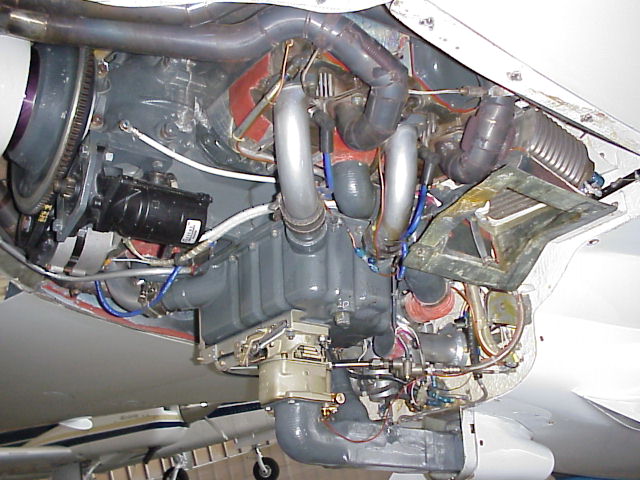
Just to prove a point, this is a picture of the engine who owns the Central States News Letter. I received it from a friend. Do you see any Thermocouples on the lower plugs or bayonets? NO, he is taking his temperature readings from the cool side of the cylinders. So, in the event he reads this page, I can help his memory out. Your taking the CHT's from the side that the cold air is blowing all over your thermocouples. You might as well put your finger in your #$$ and guess at the temperature. Next time remember to tell builders this little honest piece of information before you go quoting 250 degrees F CHT'S. By the way, You're welcome!
Long EZ Pre-buy Experience: Top of Page
So, I’m looking to purchase a flying Long EZ. I have cash in hand. The excitement of owning a Long EZ is just indescribable. It starts off with my engineering cube mate telling me that I should contact this guy called Poodle or Beagles, anyway something like that. So I end up contacting this Poodle or Beagles fella and he says that he can help me find a flying Long EZ. He states that his commission is 6%. I don’t have any problems with this, after all, this guy is knowledgeable, knows the aircraft he represents, knows the history and the builders of the planes and in addition he will be making all the phone calls organizing the meetings and assisting in the sale/purchase transaction. After all 6% is a hefty fee to pay a stranger for doing nothing right. Not in Poodles eyes. Poodle ends up sending me a faxed hand written list of about 30 airplanes (Longs and Veri’s). He then tells me over the telephone “that he would appreciate it if I updated and made changes to the list of planes, you know if they have sold or phone numbers changed, etc….”. Well, I’m thinking OK, but what am I paying you 6% for.
It got worse from there. Most of the planes on his list were so old that they had been destroyed or sold. Some of the owners had been dead for years. The list was so outdated that only 3 of the planes on it were in flyable condition and were still available for sale. By this time, its cost me a few days and several dollars to call people all over the United States looking for a viable Long EZ from his outdated OLD F***ing LIST!!!!
I find a man in St Louis that has one for sale. He told me that he hadn’t flown it but 40 hours in the last 10 years. He said he had never left the airport traffic pattern. Wait, before I continue on, this guy also had listed the Long EZ in Trade-a-plane that I had looked at almost a week earlier. Keep in mind I was going to use a professional to help me find a Long EZ, that’s why I contacted Poodle. OK, let me finish where I left off. So, this guy had been afraid to leave the airport traffic pattern for ten years. I ask for some pictures and the background of the plane. Keep in mind that this Poodle fella has not gotten involved in the picture yet. After about a week I get a call from Poodle and he asks if I found a plane. I then tell Poodle I’ve been working with a seller out of St Louis and will be paying all expenses for the seller to fly the plane to Michigan so I can see it. In the mean time Poodle hasn’t made one phone call or coordinated a damn thing. All he had done was sent me an outdated list of planes and asked that I make the corrections! I decide to make Poodle work for the 6% he wants. I tell him I need the history on the plane and some coordination help. Poodle replies that he knows nothing about the plane or the history and has never met the builder or the owner. Imagine the vain in my forehead when he said that. I’m thinking, just what the hell is it you do for a 6% commission?
Poodle says that I should contact his friend at Pontiac airport and his friend could help me with the pre-buy. By the way, his friend is the man I refer to in the oil filter incident. Of course that hadn’t happened yet. Anyway, Poodle gives me the number of his friend at Pontiac. We get together and meet the seller of the Long EZ at the airport. Keep in mind that I have covered all travel expenses to get the plane to Michigan, phone calls and coordination. In addition, I have a car and local cell phone for the seller to drive while he is in town visiting relatives for the next 3 days. Plus I took both of these men out that night and purchase a steak dinner as a celebration for the airplane and new friend’s gesture.
The following morning Poodles friend, the oil filter guy (Jim Price) starts doing a pre-buy inspection for me. I am very grateful for the help because I know nothing about these planes. The oil filter guy is a so called guru of Long EZ’s, he's just under Mr. Rutan as a celebrity in the canard community, or so I believe this. Well after he taxied the plane and had gone through everything Jimmy Price tells me “it is a solid aircraft and to go ahead and pay the seller”. So we put the plane in a temporary parking spot and head inside the FBO lounge area. I give the seller almost 30K and he signs over the registration to the aircraft. I also forgot to mention that I had to purchase his commercial airplane ticket back to St Louis and get my loaned car from the airport as a gesture of THANK YOU for the good deal and for bringing the plane to Michigan. Yes, I was very trusting and honest.
The weekend finally comes and I can’t wait to head out to Pontiac Airport and check out my new Long EZ. I have read the owners manual and am ready to take her for a few taxi rides and then a flight. So, I get familiar with all the switches and fuel selection valve. I have memorized the owner’s manual and decide to do some taxiing. She starts up OK and as I’m taxiing I notice that the directional Gyro isn’t keeping up with the turns. No big deal I figure the RPM is low and that the vacuum will increase once I fly her. I decide to call ATC and go for a ride. I start down the runway and everything is looking good except I notice that it takes a long time to build enough speed to rotate. Pontiac has a 6000 foot runway so there was enough room.
While I’m in the air I notice that the directional Gyro and AH Gyro are non responsive. However, I have 4.5 lbs of vacuum on the 2 ¼ gage. After about 30 minutes of flight I decide to call tower and bring her in. This is where I find out that I can not pull the throttle off on final approach or the engine starts to stall. You see the spark plugs were all oil fowled due to worn out cylinders. After I get her on the ground I call the local A&P from the Lycoming shop. His name was Ken Bluemenshine, just a wonderful man. He did a compression test and found that all my cylinders were less than 62 lbs. I had one as low as 40. He tells me the bad news. I need a top end done. So about a week goes by and I begin tearing off the cylinders of my new plane. Ken drops by the plane to check my progress. He then notices that one of my cam lobes is completely gone. Now I need a complete engine overhaul. In the mean time Poodle wants his 6%. So I tell Poodle that I will send him 3% and that’s it! I shouldn’t have sent him a damn DIME! He represented a plane he knew nothing about and had a personal friend do the pre-buy that had no idea what to look for. Know I think I understand that they worked together not caring about the buyer just to get the commission and split it? I still haven’t figured it out. Either way both of these men are untrustworthy, self-serving crooks.
So, my new Long EZ hasn’t been in the air an hour with me behind the controls and I need a $9000 engine overhaul, $1500 in gyros and I haven’t found the vertical crack from the axle 18 inches up the middle of the gear leg yet. In addition, I believe my transponder is working with my altitude encoder. That was another $900 hit. So you can understand why I have no use for that Poodle / Shit-zu fella. He was just a scam artist advertising himself as a canard finder. He wanted nothing to do with what had gone wrong with the plane that he received a commission for. And you can also understand my dislike for friend that did my so-called pre-buy. He either intentionally screwed me or had no idea what he was doing. But, since he built his own Long EZ I’m guessing it was an intentional dry lube encounter. At the time I forgave and forgot. But this guy would screw me with little things all the time. Finally after the oil filter incident I decided this guy was just a rotten individual. Fortunately I relocated to another airport and we don’t run into one another any more. Last I heard he was taking pictures of pilots & canard Aircraft at Rough River and then trying to charge them for a digital file copy. The good news was a fellow pilot started a USB download of his camera while he was off trying to extort money out of another pilot for a digital copy of a picture he had taken.
And some of you wonder why I have an attitude towards a few of the old guard Long EZ builders. It’s easy, Once you've been bent over for 11 grand your ass hurts. These few bad apples are self serving and don't share information. In addition, they openly lie & cheat others! They are willing push morals aside and do whatever it takes to someone so long as they receive a financial gain.
For those of you that are new canard owners or want to be new canard owners be aware that this hand-full of the old guard feel you are not worthy of information because you didn't build your plane. I think it is because most are getting old and mean. They are becoming spiteful of the new generation stepping into a Rutan cult community of flyers that they had locked up for 3 decades. In their minds, you haven't paid your dues or earned the right to be part of the community. Your life may be at risk, be careful who you trust, I learned the hard way. The two guys that screwed me didn't give a damn if that plane fell out of the sky so long as they got the sale commission. Don't let David Orr represent you or your plane. As a matter of fact tell him Phil Camarda told you to steer clear of him.
Note: AKA Poodle, Shit-zu or Beagles also goes by the name (Canard Finder and David Orr).
Building Planes Top of Page
How many times have you gone out to the garage with a cup of coffee and done nothing. How many times have you sat at your desk at work and thought about a building process. How many times have you spent time on the phone talking to a buddy about a particular subject that is related to your project. Now look at all that time and just think if you would have devoted it to actually putting something together. Welcome to the building process. I am a builder! No I am a pilot that is to cheap to buy a plane so I build them. And then they cost more than it would have to buy one but they are so cool and cheap to fly and I just love all the guys that build and fly.
That being said Phil has said that I am a fast builder and I have heard that from several other canard builders and my statistics kind-a bare that out 4 rebuilds in 9 years. Did I say there was a divorce in there too. Ok so I have an advantage I am a single guy. But still, how do I do that? I also work a full time job and have moved no less than 4 times in that time frame.
Ok here is the secret. Do something..... That's it just do something every day or as often as you can. Some times I go for months without doing anything that's usually in the summer when I have a plane to fly. or I get burnt out. I love all of you guys but get off your computers and get out there and build. A good friend of mine told me after I finished building my first plane that you are not the student anymore you are the teacher be careful what you tell people and teach. Although I have strong opinions about certain things and if you ask me I will certainly tell you but I don't write articles on how to do things. I share my knowledge with those that are interested but beyond that I keep my head down make lots of mistakes do things over more than once but I do build and complete planes. So that's my secret just go out there and do it. And if you think you know more than Burt then design your own plan and leave his alone. See there is that opinion thing again.
Feel free to come by and visit I usually have a project in the garage..
David Hanson
600 Woodside Ave.
Ellwood City
PA 16117
Ph 724 614 9046
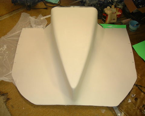
The Dave Lind Lower Cowling Top of Page
A few years ago I had the opportunity to recover one of Dave Lind’s extra lower cowlings to his Long EZ. You see, a local friend had purchased Dave’s plane and the extra lower cowling came with the sale. The cowling was rumored as one of the keys to the incredible speeds Dave could ring out of his beautiful Long EZ.
The owner of Dave’s plane ended up selling it to that Poodle, Shit-zu / Beagles fella. However, he did not sell or include the lower cowling with the plane. I asked the owner (friend) if I could make a copy of the cowling. He said yes and had no issues with granting permission. The only obstacle was to get it released from a fellow canard driver that thought he had the rights to this extra piece of fiberglass. Yep, here we go again with that guy out at Pontiac that helped with my pre-F***ing, oop’s I mean Pre-buy of my Long EZ. Remember this is the same guy that offered that outstanding advice about the oil filtration system. Some how this guy was storing the extra cowling in his hanger. Well the gentlemen wouldn’t give it up so I called the cowlings owner again and had the owner contact him and state that it didn’t belong to him and he was to hand it off to either me or one of my fellow long EZ buddies ASAP. Needless to say after weeks of excuses the man ended up surrendering the cowling that did not belong to him. I have to admit it felt good knowing this guy had to give this part up. It was like I had a chance to lube him up for once.
Well a few months later another fellow Long EZ driver made a beautiful production mold from the extra Dave Lind lower cowling. The first part pulled from the mold was manufactured from Carbon Fiber. It was extremely light and very robust.
This lower cowling was fitted and attached to his Long EZ airplane with no other modifications to the aircraft. An addition 6 knots were obtained instantly just by adding the lower cowling to the plane. Once the cowling was tweaked a bit and a few other modifications completed to enhance the cowlings performance an additional 8 knots were gained. So the new lower cowling with a few changes to the center line location, rear taper angle and increased flow attachment produced a solid 14 kts of reduced drag or indicated airspeed. There is something to be said for taking a good part and making it a phenomenal part.
The cowls performance data was never really disclosed up until today. I mean, I flew along side of this aircraft for several years and was amazed at the initial speeds. However, It made no sense in releasing the information without having a place to publish the results. Plus I’m told that the original mold of this cowling was purchased by that fella I keep referring to at Pontiac. He along with a few other old guard canard flyers were going to make and sell these Lind cowls. I just hope they understand the center line location, rear taper angle and increased flow attachment blending to achieve the same results before they start selling copies.
It’s amazing what you can achieve if you take the time to test, compare and validate the results. One small bit of advice, never try and validate or test more than one item at a time or you will never know what change was responsible for the results you achieved. Isolate all modifications, test all changes compared to a base-line. Record data for every test attempted. Make notes of your results. It all pays off in the end!
How to Quantify Data Top of Page
Understand the basics for recording testing and evaluation of changes to the airframe or power-plant. I learned this as an engineer and a Military test pilot in the Army. Every test was evaluated to a base-line. Shooting from the hip produces poor results at best.
Consider this; every time you take your aircraft for a flight the conditions are different. The variables rang from wind direction to wind speed, temperature, humidity, time of day (thermals) and even engine temperatures (Oil and CHT’s) playing a part in the performance numbers you’ll get.
You need to have a base-line to test from. I usually picked early morning with temps in the mid 60’s to high 70’s. Full fuel tanks, No winds, no thermals building yet and clear visibility. In addition I would always test with engine throttle at Wide Open position from take-off roll through a 500 ft per minute climb to 3500 ft MSL. Then I’d lean at 3500 ft and let stabilize for 3 minutes (no vsi movement). Check clock and have elevator trim adjusted at this point. That usually put me near or over a specific land mark on the ground. Once I hit the 3 minute stabilization point I would collect the data I was testing for. That was my base-line. Every test flight from that point would be identical from Take-off roll through 3500 ft with the 3 minute stabilization. All flights would be towards the exact same reference point on the ground (heading). This could be a bridge, lake, tall hill or even a highway. You just need a repetitive reference point to fly to for each test.
At minimum you want to record the following. Temp at altitude (3500 ft msl), Indicated airspeed, Propeller RPM, (for temp testing get CHT’s and oil temp). Each end every test should be executed the same way and compared to the baseline numbers. A very close friend (Gary Ernest) and I decided many years ago that neither of us would ever quote a performance or cooling result to each other without testing the before and after in the manner described above. We didn’t want any outside influences or fudge factors affecting our results. Both of us actually quantified our failures and improvements through proper data collection.
I remember testing different cowling designs by duct taping different contours / shapes that I had made to my existing cowling. I would modify my cowlings outside shape with glass molds and then test for performance increases. It took hundreds of hours and dozens of trial and error flights before I found the results I was looking for. Imagine if I had not collected the data identically for each flight. The numbers couldn’t be trusted, the results unconfirmed. My buddy Gary Ernest is the exact same way when it comes to quoting speed or performance increases. He wants to know the before and after results under identical conditions. All his testing is done the same as mine. The information we have shared between us has produced some incredible results in cooling and aircraft speed. That’s what you get when each of you can quantify the results and be able to identify exactly what got you those numbers.
Below is an example of just one part I conducted testing with before making permanent changes to the cowling. This was one of three different generations of the same part that I tested before getting the results I was looking for. Each test took time for set-up and data collection. It's time consuming to do it right.
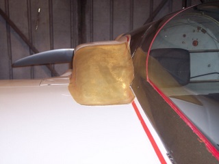
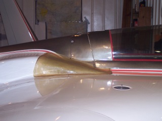
Another issue I want to touch on. Never, NEVER, test two modifications at once unless you’re willing to quote them as a combined loss or increase. I’ll give you an example. Some of us like to put different wheel pants on our planes and then add gear leg fairings. Wheel pants may increase the overall speed of the plane but depending on the gear leg fairings you may be adding additional drag. I’ve seen this happen. The end result was NO quantifiable change in airspeed. Although the owner of the aircraft has a hard time admitting this because he just spent 1500 dollars on pants and fairings and didn’t see that significant increase he was looking for let alone paid for $$$. Each test should be independent of the other. How many of us have worked for weeks on a speed mod or cooling mod and gone out testing after our bird was down for a month or so and then justified the failure or increase with time of year or outside temperature changes or even how much fuel we have on board. The goal is to create a testing environment that leaves little to no room for error.
As a first test I recommend that you try this with your airplane. Create the base line I spoke about earlier. Then take a second flight moments afterwards and leave your front landing gear extended for the test flight. Record the numbers and compare them to the base line numbers. That will give you a true indication of how much drag the front landing gear caused to the airframe. If you do everything off a base-line you’ll only have one variable involved, the front gear.
There is one more thing I’d like to talk about; purchasing performance modifications like cowlings, gear leg fairings, wheel pants, props and NACA inlets. If I was a manufacture of these components I would or at least should be able to quantify the gains or losses you may experience with my parts. After all, you’re spending a lot of money on parts that are suppose too give you more performance right. These parts should come with some sort of quantified testing. You should be able to ask, what kind of speed or performance should I expect to gain from a set of particular wheel pants or gear leg fairings? I mean there should have been some testing prior to the claims right? I’ve noticed that the propeller manufactures can usually tell you over the phone what to expect from one prop to another. Never be afraid to ask questions about performance or cooling parts that are being offered for sale. Ask, EXACTLY what will this due for my airplane? If the part is proven and tested against base-line testing you should receive a quantified answer. Like I said, I was a test pilot and currently an engineer. I expect, hard data, guessing or speculation is something I’ll let the non professionals and fools accept as fact for spending their money. I’m looking for the test data. Imagine if when I designed and released an engine controller it was done off speculation that it would operate at high RPM’s, work better than the competitors and operate when it was cold out. Yet, I don’t have any numbers to prove it because I am guessing and never tested for specific results. Demand good data from yourself and those that sell you parts or feed you information. If you want to go fast and stay cool it’s your only real option unless you have deep pockets and like to do work over and over again hoping for results.
Nothing comes for free in this business especially from those you’re competing with. Ask questions, quantify results.
Long EZ Engine Failure (ENGINE OUT) Top of Page
Are you a member of the engine out club? One thing is for certain if you are you handled it right or you wouldn’t be reading this. If your not, odds are you will be some time in your general aviation career.
I remember training for engine failures with an instructor in the military. When the simulated engine failure took place you were told to take the bird to the ground. That was in helicopters back in the mid 80’s. Later they made you recover with power as you were flaring for the ground. Then in the civilian world the instructor would put his hand on the throttle directly in front of you. If this wasn’t enough advanced warning I don’t know what is. He’d pull the throttle to idle and let you run through the fuel, mags, best glide, transponder, mayday and restart procedures as you picked out a field or a road to put her down. Always in daytime and always over a training area with several landing spots.
So here is the real deal. Most engine failures take place under not so ideal conditions. They happen when you least expect them to and usually over an area that provides no safe or survivable landing sites. I’ve had several emergencies equivalent to an engine failure while flying military aircraft. I had a crew-chief once forget to put the cap on the hydraulic reservoir and then washed the helicopter. The reservoir filled with water. During the formation flight at tree top level the controls became extremely hard to control, they were fighting me. I had water boiling in the hydraulic lines forcing the system pressure in all different directions. No emergency procedure equips you for these situations.
I remember breaking off from the formation and struggling to control the bird from entering the trees at 90 kts. Finally being able to grab some altitude and try figuring out what was happening. Even with the hydraulic pump off, the controls had their own mind. I fought the ship to a local airfield and did a run on landing on the skids knowing I couldn’t control the ship in any type of controlled hover to the ground. Another time I had a turbine compressor stall while NOE (nap of the earth) picking my way through the tree tops at 40 kts. They tell you about these things in training but until you experience them you have no idea how incredibly scary and life threatening they are. The bird jumped 90 degrees around the rotors axes so fast it slammed my helmet into the B-pillar behind the door. It did it again within seconds. Each time it sounded like a grenade went off. At this point I thought we had hit something the force was so violent. You would have thought the tail boom had left the aircraft. I managed to set the Huey down in a clearing just big enough for the rotor to clear the large branches.
The experience that caused me to suck the most seat cushion up my rear end was when flying the Long EZ one evening on a moonless night. I had called my buddy Vince up on Thanksgiving eve around 8:00 PM and asked if he felt like going for a flight. Anyway we headed out to the airport that evening and jumped in the Long EZ, it was cold out, around 30 degrees. We performed all the pre-flight checks and departed to the west. It’s important to note that the engine was just inspected by the shop (Lycon Engine Overhaul Facility) that had overhauled it. So, I climb up to 6500 feet MSL and leveled off, the flight was smooth as silk, the sky and ground were dark as coal. About 10 minutes into the flight I ask Vince if he’d like to fly her (Vince has 20 hours in small planes working on his license) while I punched in a few waypoints in the GPS. The second I put my head down to program the in-panel Garmin the engine QUITS! IT JUST STOPS! Like someone turned the key off. Not a sound except the whispering of air sailing over thin skin of the long EZ canopy. I'll always remember the eerie silence of my Long EZ Engine Failure
Vince said "did you do that". I said NO! Then I took the controls and went through the standard engine out procedures, called on 121.5 set 7700 up in the x-ponder and announced my situation to ATC. All this was going on while I'm reaching for more altitude bleeding off 140 kts for 90 (best Glide). I looked at the little 1 inch manual fuel pressure gage on the panel. It showed what I thought was zero pressure, or so it appeared. Anyway, thank god Garmin had the nearest airport feature built into the GPS. I was 8 miles west of Howell airport in Livingston Co Michigan. I turned the bird around and began the long glide back. The ground was just black like coal, you couldn't tell roads from fields, lakes or trees. The engine is wind-milling at this time but will not fire. I was a bit high when we reached the airport I had to go past it on the downwind to slow and lose enough altitude to make the runway. I remember Vince saying calmly "hey Phil your going past the airport". Well, we made the landing without issue. I called ATC immediately from the FBO and told them we were down without incident at Howell. They had told me on he radio they lost me at 1500 ft MSL. The old gentlemen in the FBO says to me "I didn't even hear you come in". Vince says without missing a beet "gliders are hard to hear"!
Shortening the story, the engine breather tube had iced up with moisture causing the crank-case to pressurize. this put additional pressure on the engine driven fuel pump diaphragm causing excessive fuel pressure. The carburetor needle and seat could no longer hold back the excess pressure and allowed the fuel to vent up the venturi. This flooded the engine and fuel fouled all the spark plugs. It was the engine overhaul shop that routed my aluminum breather tube on the cold air side of the engine. That little fuel pressure gage was actually pinned out with pressure. The needle wasn't setting on zero it was pressed up against the back side of the little pin it usually rests on when there is no pressure. Just another lesson in the little things that can take you out of the sky. So when you least expect it, be ready for it.
Downdraft Cooling Design Top of Page
Downdraft cooling is not as simple as mounting inlets facing forward and catching the relative wind. It involves a few complex issues that must be dealt with properly. First of all the inlet design must be one that expands the incoming air. It takes high speed low pressure air and converts it to low speed high pressure air. This is essential to get proper cylinder cooling.
There are many opinions related to what works best to accomplish this low speed high pressure air design. The concept that worked for me was to use a funnel type inlet, bring the air in a 4 inch wide opening and then expand the openings width as the air travels back to the cylinder plenums. My inlet side walls expanded at a rate of about 5 degrees. However my design was rectangular in shape. I was trying to blend a cosmetic design into the plane. The most efficient expansion design is a funnel or expanding tube with smooth walls. However, before you start building your inlet design you need to understand what type of volume will be required to cool that fire breathing continental or Lycoming dragon.
Rule of thumb through experience and many iterations of test flights of several aircraft. A 4 inch high by 6 inch opening or 24 square inches is the minimum inlet size to cool 160 hp. That equates to 12 square inches per side of cowling for inlet opening. Add an additional 2 square inches per each 20 hp. You can go smaller but you will struggle with CHT’s. I’m not telling you how to design your inlet size, I’m telling you what works for those of us that have done the testing and modification to downdraft cooling. You can build whatever you choose. Keep this in mind; the inlets should not interfere with airflow to the propeller. They need to be designed and positioned in a manner that allows efficiency yet does not impede on prop performance.
The next step in downdraft cooling is a cylinder plenum. The plenum must be large enough to allow the air to expand and completely seal on the top of the engine. Any small leaks will allow the pressurized air to bleed off and not complete the intended path through the cylinder fins. Air is a lot like electricity or even people it will find the path of least resistance and take it. So make sure you have a good sealed plenum. In addition you must allow for engine roll so the inlets that connect to the plenum must be flexible or they will crack the fiberglass duct work.
In addition to inlet size, expansion walls and a sealed plenum you must provide cylinder baffling on the bottom side of all cylinders. You need to direct the airs path to flow through and around the cylinder fins. The openings between baffles should be about 1 to 1.5 inches. If you don’t baffle the lower cylinders you will not have even cooling. The cylinder tops can remain open to the incoming pressurized air.
Next you have to allow for the hot air to exit the rear of the cowling. Sometimes this is difficult due to the cowling opening being small. The propeller acts as a big air buffer at the back of the cowlings. The exhaust air has difficulty getting past the pressure pulse that the prop creates between it and the cowlings. You need to make sure you have adequate venting at the back side of the aircraft. Do not close up the cowlings to tight or you’ll have engine CHT issues. So allow for the cooling air and exhaust air to exit the rear of the plane. You’ll need 2 to 2.5 times the exhaust area as the intake (Engine inductions system, oil cooler and cylinder cooling).
If you can put all these items together you should have a very well designed downdraft cooling system. The last thing you need to do is place the CHT probes on the underside of the Cylinders. You can use the bayonets or the spark plug ring type. The plug ring type will read a little hotter than the bayonets. Keep in mind that the plug ring thermocouples are true. They are extremely accurate and read exactly what the CHT is at each cylinder. The bayonets may read a few degrees cooler. Do not take your CHT’s from the cool side of the engine (top side or air inlet side). You will be seeing a distorted temperature, some by well over 100 degrees F.
So, the basics for good dependable downdraft cooling an a canard / pusher aircraft are, correct size inlets positioned in an area that will catch the relative wind, air expansion chambers, sealed plenum, cylinder baffles and a large exhausting area.
Battery, Starter, Terminal Connections or Cables? Top of Page
A few months ago (mid February 08) I went to the hanger and tried to start the airplane. Before I tell you what happened I need to provide some background. First, I always keep my airplane on a digital battery tender (.5 amp max charge rate). In addition, I have always purchased premium aircraft batteries. The current battery in the airplane was an Odessey 925.
So, I’m going to start the airplane after about 60 days of setting in the cold hanger. I hit the key and she groans and struggles to bring the prop past the compression stroke. It does this several times. Very slow crank, almost coming to a complete stop at each compression stroke. I start to think about it and have determined that the engine has been cranking slower and slower over the last 6 month. I figure it must be the battery even though the Odessey had only been in the aircraft for less than 5 years. Plus, it was always maintained on a tender.
I decided to purchase a new battery from the local Auto-Zone. They sold those cool looking Gell Cells with the round cylinder looking shapes, Optima. These batteries can be mounted in any direction or orientation and will never leak. The price is a bit steep $190.oo but there are 650 CCA. I figure the battery would be able to crank my prop like it was idling. I installed the battery after making a new battery box top and bottom. Attached the charger to the battery for 24 hours. When it was time for me to start the engine it didn’t spin much faster than the last battery. So now I’m thinking that maybe I’ve got a loose connection or a bad starter. I check the battery voltage 13.77 volts. Yet the engine is hardly passing the compression stroke.
I figure that it must be the starter. I am very fortunate as I have a frame that an automotive starter bolts into and then adapts to the Lycoming Starter pad. I head to the auto-parts store and purchase a Toyota Land Rover 6 cylinder starter. It bolts up to the existing adapter pad. After an hour of installation I hit the key and the engines cranking performance has not changed, it is just barely getting past each compression stroke. My next thought is check all the connections at the battery, master solenoid and Starter Relay. I took the entire system apart and inspected every connection. It looked great so I put everything back together. What could it be, I’ve got it, I received a bad starter. I’ll pull the starter and exchange it for a different one. After putting a 2nd new starter on the airplane nothing changed.
I’m just puzzled at this point, new battery, new starter, I’ve checked all the connections and the engine is still acting like it did before. I decide that there must be corrosion in one of the long 04 battery cables that go from the front of the plane to the rear. I purchased 40 ft of 02 welding cable and all the terminal ends. I made all new soldered terminal cables and install them on the airplane. In the mean time the battery charger has been keeping the battery charged. I figure that this has solved the problem and turn the key. Nothing has changed. I pull the battery out and take it back to the auto-parts store because it wasn’t an aircraft battery and I’m running out of things to trouble shoot. I head off to WEST marine and purchase ($109.00) Glass Mat Sealed battery just like the one that many of my buddies have in their Long EZ’s. It’s the same battery ACS sells under a different name. I charged it over night and install it in the Long EZ. The following morning I attempted to start the Long and all I got is groaning and trying to get past the compression stroke. I’m at a complete loss so I contact Sky-Tech and tell them I don’t know where else to look, maybe I needed to install a 7:1 hi-torque aircraft starter. The owner tells me that it isn’t the starter. He says it’s the battery. I re-emphasize that 2 brand spanking new batteries have been installed in the aircraft and it didn’t do any good.
The owner of Sky-tech asks me to put a voltage meter across the Positive and Negative terminals of the battery while the engine is cranking and check the voltage. I finally call a buddy to the hanger and ask him to crank the engine while I check the voltage at battery. During cranking the voltage dropped from 13.75 to 6.4 volts instantly. The owner was right. All 3 batteries were bad. None of them could support a load. However, they check out just fine on voltage and the battery charger.
I ordered a 3rd new battery from Aerobatteries (http://www.aerobatteries.com) in Texas. Made them load check it before shipping. I installed it and hit the starter button. The engine cranked like a champ. All that work and time because of defective batteries.
So, my Long EZ has all new battery cables, cable ends, starter and Gell battery. Being an electrical engineer I should have checked the battery first. But who would have thought that I could have purchased 2 defective batteries in a row from two different manufactures from two separate stores? Lesson learned, always go back to the basics when trouble shooting an issue.
Going Fast Top of Page
Everyone who owns a canard aircraft or is building one talks about doing modifications that add speed / performance and control cooling on the airplane. I have spent hours reading the different forums on how to go fast or control cooling. The theories are all over the board. It always amazed me that builders who haven’t flown their aircraft yet manage to have the answer on how to cool an engine or control air flow over a cowling or winglet. Most non flyers will tell you how to go fast without ever doing a single test. They’ll talk about winglet radiuses and pressure recovery and even aerodynamic formulas.
There is nothing wrong with any of this. However, the fact is, unless you have made the modifications and tested them yourself at SPEED, not at vehicle/car speed but at actual aircraft speed attached to the airframe under different attitudes (climb angles and weights) you have no idea if the modification will work or not. I’ll give you an example. A cooling modification made to my outer cowling blasted plenty of air during testing at 70 and 80 mph. However at 160 mph the air skipped right over the top of the inlet. Oil flow and temperatures showed the inlet wasn’t working on the airplane. This is because the change in speed caused boundary separation to happen at different velocities over a curved surface. It’s the same thing with ram air ducts. The oil cooler or surface you are trying to force air through to draw heat away can only pass so many cubic feet of air per minute. Once you exceed that maximum flow other aerodynamic changes start to take place. An invisible pressure bubble similar to a glass shield starts to block the inlet opening. This pressure bubble then begins to disrupt the flow so much that the incoming air is no longer efficient. Turbulence from this pressure bubble has effectively made your cooling efforts ineffective. Furthermore, it has increased aircraft drag tremendously. So what works at some speeds doesn't at others.
Keep in mind, it’s not just about how much air you can capture and flow through a coolers grid or engine cylinder fins. You have to account for the heated/expanded air to escape. Remember high pressure in the front end once heated creates higher pressure on the rear end. You need to provide a means of vacuuming the pressurized / heated cooling air away. You need a lower pressure relief on the backside. Unless you have a difference in Delta-P your cooling will be inefficient and the drag will be increased. The end result is hot engine oil or cylinders and reduced aircraft speed/performance. Always keep this basic physics law in mind “For every action there is an equal and opposite reaction”. The three things that affect all this are aircraft attitude (angle of attack), weight and velocity. If any of those three factors changes everything else changes. All designs must be engineered for a specific range in velocity, weight and attitude to be highly effective. This is why so many people do not realize the same results others do when installing the same modifications. Even though it’s the same design and airplane, there are many differences between aircraft that are plans built.
If you want to go fast you need to speak with people like Gary Hertzler or Klaus. I once sent Gary pictures of my airplane and asked “how can I make it faster” He wrote an entire page of things that I needed to do just to make it efficient. The secret to going fast is as any racer will tell you, lite aircraft, powerplant and drag reduction. Next come the basics, clean airframe (reduced parasite drag). Straight airframe (fly’s true). Efficient propeller (Gary Hertzler makes one of the best). Effective cooling of engine and oil cooler (low cooling drag, reduced inlet sizes). Correct canard and main wing incidence. Just a degree of incorrect wing or canard incidence can cause tremendous drag at higher speeds. The canard and main wing start fighting one another. The main wing wants to climb due to its airfoil shape and the canard must be positioned to maintain altitude (Negative). This starts to take place at about 160 knots even with proper wing incidence. If you're running out of down trim you’ve experienced this issue.
If you have everything taken care of that I have just described above then you can start adding items that will assist with performance. First, electronic ignition is a great place to start. It removes the drag from the engine gear train and increases ignition performance. Next is a 4 pipe exhaust system to let the engine exhaust easier. In addition you may want to get rid of the factory design air intake system and go to a ram-air design to increase the engines breathing. The cosmetic things that add a little performance are wheel pants and gear leg fairings. You may want to enclose your front landing gear so the belly of the plane is a bit slicker. These are all proven items that will help with aircraft performance.
The one thing you must understand, most of the guys going fast are not running stock airfoils. They have changed the wings design and or the incidence of the wings. In addition they have no niceties in the plane, the luxury items are stripped out for weight loss. They have only basic instrumentation to save weight. In addition, the engines are pushed hard. They don’t care if they make TBO or not. They have a goal and that is to win the race. So in order to competitively compete with the fast racers of canard aircraft you have to make some creature comfort sacrifices and some other more critical modifications.
I’ll share this one bit of performance information with you. Should you modify your airframe or cowlings, sharp or small radiuses make you go fast. The larger the radius transitions the more drag it will produce. I am speaking of radiuses that run in parallel or with to the relative wind. The larger more transitioning radiuses look nicer but don’t help with performance. So, cosmetically appealing or FAST, your call. One more tip. All airframe surfaces should stay within 8 degrees of the relative wind or you will have disrupted air flow, it will separate from the aircraft skin causing drag. Note: See Harry Manvel's rear cowling on his Defiant. He fixed the issue with VG's.
Next time you’re around Gary’s or Klaus’s airplane, don’t just look at the airplane study the subtle differences in the trailing edges and the vertical to horizontal transition radiuses. Look at what you normally wouldn’t pay any attention to and you’ll see why they go fast.
P2 engine Install P3 Upper Cowl P4 Lower Cowl P5 SPL Parts P6 Flt Pics P7 More Pics P8 Bio Info
P9 Engine TBO P10 Tips & Tricks P11 Your uploads HOME PAGE
Rutan Long-EZ aircraft pictures. Rough River Kentucky Fly-in pictures. Aircraft Pre-buy experience with David Orr and Jim Price. Long EZ cowling performance. Facts about downdraft cooling. Long EZ engine failuer. Long EZ engine out at 8000 ft msl Long EZ engine failure at night. Engine failure at night in a long EZ. Berkut 360 Lycoming Engine. Long EZ pre buy story. Downdraft cooling description and details. True airspeed discussion and facts. Facts about sharing canard performance information. Long EZ Power Plant is a stock 0320. Building experimental aircraft by Phillip Camarda. Recording aircraft flight data with an EFIS. Aircraft Voice recorder information. Garmin GPS systems and nav/coms. Garmin GPS Serial data Format. Recording EFIS data with a laptop. Capture Serial data. Aircraft EFIS Flight Instruments. Electronic Flight Instruments used with Aircraft Engine Monitor System. Garmin G format. Infinity landing gear on a Long EZ. Plans Built Airplane. Oil Heat system for Homebuilt airplanes. Long EZ Canard and main Wing. Dynon instrument panel in a Long EZ. Garmin Serial Data Format. Grand Rapids Technology EFIS Systems. Long EZ Nose gear electric motor. Long-EZ main landing gear wheel pants. Long EZ landing gear doors. Custom LongEZ parts and components. Lycoming engine in Long EZ. Gary Hertzler Propeller with 6 inch propeller extension. EZ Nose Lift retractable nose gear for Long-EZ. Rutan Long EZ is a plans built aircraft. High speed homebuilt airplane. Retractable landing gear for Long EZ. Custom Velocity parts and components. RS 232 Serial data Format. Custom Cozy mouse cursor pointer. Custom Aerocanard airplane parts and components. Custom E-Racer parts and components. Custom Canard airplane parts and components. Custom Long EZ downdraft cooling inlets. Custom SQ 2000 parts and components. Custom Experimental airplane parts and components. Long EZ Hydraulic pump. Retractable landing gear for a Long-EZ. Custom veri ez parts and components. Landing gear door rigging. Downdraft cooling for LongEZ. Speed brake installation. How to collect Flight Data. Long EZ Baggage pods installation instructions. Long EZ Intercom installation. Major airframe overhaul of plans built Long EZ. Weight and balance for a Long EZ. Weight and Balance spreadsheet download for a Long-EZ. Long EZ fuel system design. Wing adjustment to a Long EZ. How To remove the canard from a Long EZ. How To remove the engine from a LongEZ. Long-EZ Downdraft cooling for a Lycoming O-320. Long-EZ Wing Removal and installation instructions. Waiters Retractable Landing Gear Controller. Landing Light installation in LongEZ. How to Put several longezs in one hangar How to install. Retractable landing gear in a Long-EZ. How to install DownDraft cooling on a Long-EZ Neat Canopy stay system for an EZ. Cabin Heat using engine oil as source. Cabin Oil Heater for a Long EZ. Icom Radio in a Long EZ. How to Build a Manometer. Long EZ Electrical system upgrades. Grand Rapids EMS. Long EZ Cowling for downdraft cooling. Record holding Long EZ flights. Using linear actuator for a retractable Landing Gear in a LongEZ. Airspeed vs pressure lookup tables. How to build a homebuilt airplane. EZ Nose Lift installation. Landing Gear wheel pants and gear leg fairings. Landing Gear leg bow for LongEZ. Landing gear doors. Give me a percentage for doing nothing David Orr the canard finder / con artist. Beagle the con artist/canard finder David Orr. Dynon installed in instrum ent panel of a Long EZ. Dynon EFIS D10A installed in instrument panel of a Long EZ. Plans Built Long EZ. High G turn in a Long EZ. Strong Pitch Trim system installed in a Long EZ. Strong Pitch Trim mounted on right Side of Long-EZ. Long EZ Take off roll. Long EZ Landing roll out. 0320 lycoming engine in a Long EZ. Blue mountain efis in experimental aircraft. Take advantage of new canard buyers con artist David Orr. Con Artist Dave Orr the Canard Finder. Con Artist David Orr the Canard Finder. Poodle the Con artist know s David Orr. Canard Finder and rip-off artist David Orr. Give me your Money Canard Finder David Orr. Pre-buy experience with con artist David Orr. Canard Pre buy experience with con artist David Orr. Canard Finder pre buy experience with con artist David Orr. David Orr has no idea what an aircraft broker does. David Orr the con artist Canard Broker. Don't trust your life or money to David Orr he canard Broker. Canard Finder and con artist David Orr. EAA, grand rapids technology EFIS, GRT EFIS. Speed brake, electric nose lift, downdraft cooling. Aircraft speed mods. Aircraft speed modifications. Speed tip to go fast. Increased speed using modifications.